
A Precise Control Method of Buffer Oil Cylinder

A buffer oil cylinder, precise control technology, applied in the direction of shock absorber, spring/shock absorber design, shock absorber, etc., can solve the problem of low adjustment accuracy, achieve high universality, wide application range, improve control The effect of reliability

Active Publication Date: 2021-06-29
WUHAN MARINE MACHINERY PLANT
View PDF0 Cites 0 Cited by
  • Summary
  • Abstract
  • Description
  • Claims
  • Application Information

AI Technical Summary

Problems solved by technology

[0004] The purpose of the present invention is to overcome the problem of low adjustment precision existing in the prior art, and to provide a precise control method of a buffer oil cylinder with high adjustment precision

Method used


Image

  • A Precise Control Method of Buffer Oil Cylinder
  • A Precise Control Method of Buffer Oil Cylinder
  • A Precise Control Method of Buffer Oil Cylinder

Examples


Embodiment 1

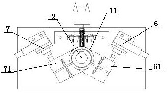
[0047] A precise control method for a buffer oil cylinder, the end of the buffer oil cylinder 1 is provided with a damping rod 11, one end of the damping rod 11 is connected to the power output shaft of the servo motor 2, and the other end of the damping rod 11 is connected to the The oil cylinder damping adjustment cylinder 12 in the buffer oil cylinder 1 is fixedly connected, the power output shaft of the servo motor 2 is driven and matched with the oil cylinder damping adjustment cylinder 12 through the damping rod 11, and the oil cylinder damping adjustment cylinder 12 is provided with a piston cylinder 13, so The piston barrel 13 is provided with an oil cylinder piston 14 slidingly fitted therewith, the inner wall of the oil cylinder damping adjustment barrel 12 is in contact with the outer wall of the piston barrel 13, the oil cylinder damping adjustment barrel 12 is rotatably matched with the piston barrel 13, and the oil cylinder The damping adjustment cylinder 12 is pr...

Embodiment 2

[0060] Embodiment 2 is basically the same as Embodiment 1, and its difference is:

[0061] The speed judgment value X in the first step is 4.


PUM


Abstract

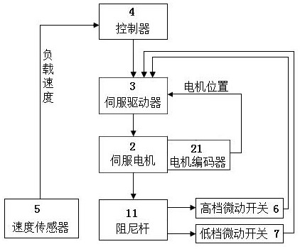
A precise control method for a buffer oil cylinder, the signal output terminals of the high-grade micro switch and the low-grade micro switch are connected to the signal input terminal signal of the servo drive, and the signal output terminal of the servo drive is connected to the control terminal signal of the servo motor connected, the signal output end of the motor encoder of the servo motor is connected to the signal of the servo driver, the signal of the servo driver is connected to the controller, and the signal of the controller is connected to the signal output end of the speed sensor provided on the load; including the second Step 1: Acquisition of load speed and sending of control commands, Step 2: PID control of servo motor rotation, Step 3: Switch feedback control, Step 4: Complete gear switching. This design is not only fast in shifting speed, but also good in reliability and high in shifting precision.

Description

technical field [0001] The invention relates to a precise control method of a buffer oil cylinder, which is particularly suitable for precisely controlling the damping of the buffer oil cylinder. Background technique [0002] Hydraulic cylinders with buffer devices are often used in the fields of machine tools, woodworking machinery, rubber machinery, steel equipment, injection molding machines, die-casting machines, marine engineering or ships, mainly to prevent the cylinder piston from moving quickly to the end of the stroke. Possible impact damage to the front and rear end caps of the cylinder block. A large winch prevents the free fall of the load from causing the winch to fly and cause damage to the winch motor; thus, an adjustable buffer cylinder is designed to protect the winch motor by buffering the free fall of loads with different weights. [0003] If the gear is adjusted mechanically, on the one hand, the efficiency of gear adjustment is low, and on the other han...

Claims


Application Information

Patent Timeline
Patent Type & Authority Patents(China)
IPC IPC(8): F16F9/50F16F9/512F16F9/34
CPCF16F9/34F16F9/50F16F9/512F16F2230/08F16F2230/18
Inventor 侯志岩杨传国周驰万志辉董新营
Owner WUHAN MARINE MACHINERY PLANT
Learn More