
Hollow-core photonic band-gap fiber based on isolated anti-resonance layers

A photonic band gap, isolation and anti-harmonic technology, applied in cladding fibers, glass fibers, optical waveguides, etc., can solve the problems of increasing the mode field diameter, increasing the core wall thickness, and roughening the surface of the core wall. The effect of limiting, suppressing coupling, and reducing scattering loss

Active Publication Date: 2018-11-30
BEIHANG UNIV
View PDF6 Cites 14 Cited by
  • Summary
  • Abstract
  • Description
  • Claims
  • Application Information

AI Technical Summary

Problems solved by technology

[0003] Although the hollow-core photonic bandgap fiber has many advantages above, its fiber loss is far greater than that of ordinary single-mode fiber. wasted
At present, there are two design methods to reduce this loss. One is to expand the core size, such as a 19-core low-loss hollow-core photonic bandgap fiber, but expanding the core diameter will lead to an increase in the mode field diameter, which is not conducive to its comparison with ordinary The connection coupling of the optical fiber, and it is easy to generate high-order modes; the second is to increase the wall thickness of the fiber core, so that the mode mismatch between the fundamental mode and the surface mode, but this can only suppress the coupling between the surface mode and the fundamental mode, and the loss reduction is limited, which cannot meet the requirements of the gyro Requirements for using low-loss optical fibers

Method used

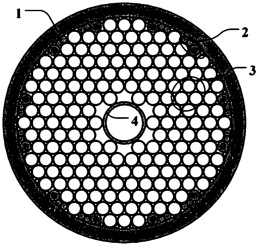
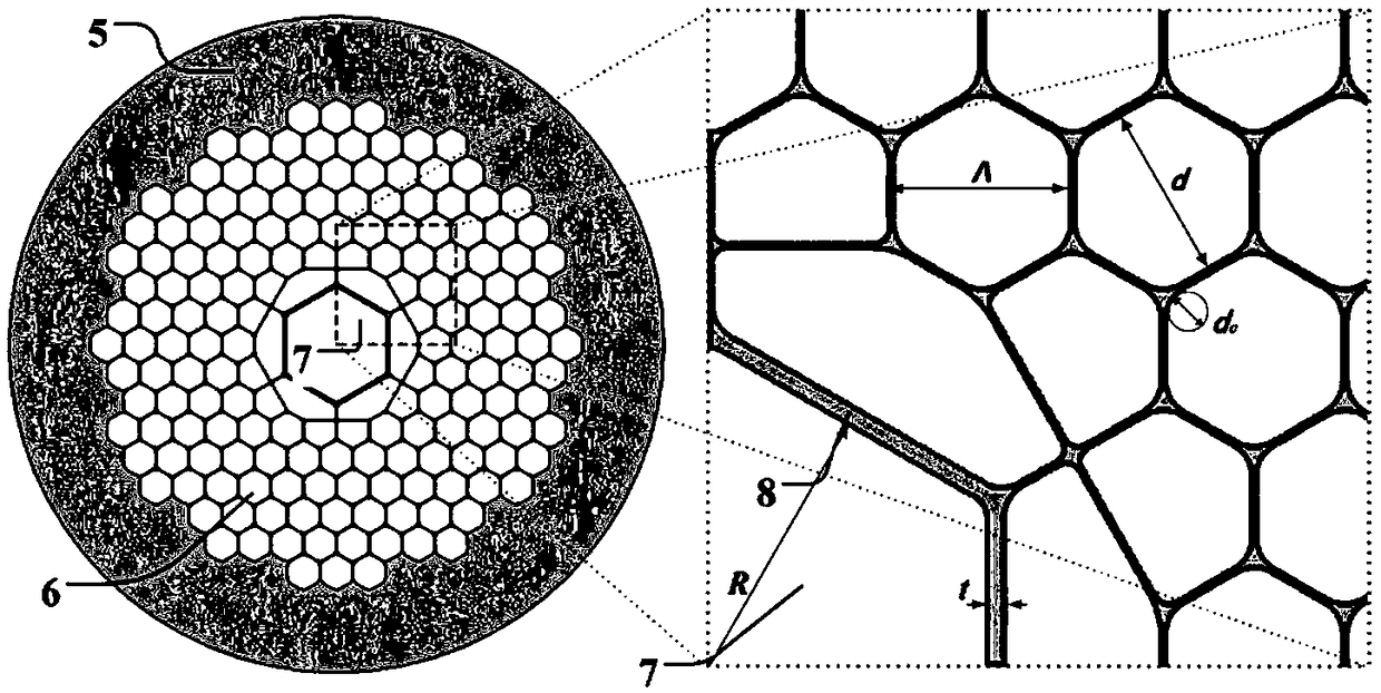
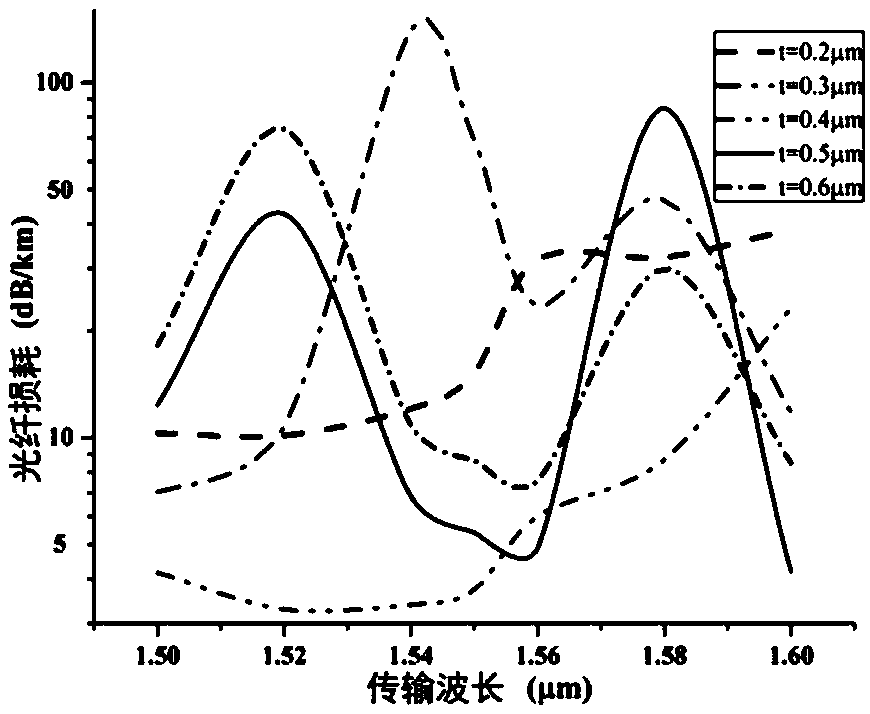

Image

  • Hollow-core photonic band-gap fiber based on isolated anti-resonance layers
  • Hollow-core photonic band-gap fiber based on isolated anti-resonance layers
  • Hollow-core photonic band-gap fiber based on isolated anti-resonance layers

Examples


Embodiment Construction

[0024] A hollow-core photonic bandgap fiber based on an isolation anti-resonance layer proposed by the present invention will be further described below with reference to the accompanying drawings.

[0025] The present invention provides a hollow-core photonic bandgap fiber based on an isolation anti-resonance layer, such as figure 2 As shown, it includes a quartz cladding 5, an air hole cladding 6, an isolation antiresonance layer 8, and a fiber core 7 from outside to inside, and an isolation antiresonance layer 8 is arranged between the fiber core 7 and the air hole cladding 6, The thickness of the isolation anti-resonance layer 8 is 0.2-0.6 μm, and the material of the isolation anti-resonance layer 8 is quartz glass; the shape of the isolation anti-resonance layer 8 is approximately a regular hexagon.

[0026] The thickness of the isolation anti-resonance layer is preferably 0.4 μm.

[0027] The distance from the center of the fiber core 7 to the air hole cladding 6 is gr...


PUM

PropertyMeasurementUnit
Thicknessaaaaaaaaaa
Thicknessaaaaaaaaaa
Radiusaaaaaaaaaa

Abstract

The invention discloses a hollow-core photonic band-gap fiber based on isolated anti-resonance layers and belongs to the technical field of microstructure fibers. A preparation method of the hollow-core photon band-gap fiber specifically comprises the steps that a complete stacked structure is formed through stacking of capillary tubes; after the capillary tube at the center of the stacked structure is removed, a fiber core glass tube is inserted; the periphery of the complete stacked structure is sleeved with a quartz sleeve to form a fiber preform rod; and the fiber perform rod is drawn through an existing hollow-core photonic band-gap fiber drawing method, a structure with the independent isolated anti-resonance layers is formed at the periphery of a fiber core, and thus the hollow-corephotonic band-gap fiber based on the isolated anti-resonance layers is formed. According to the hollow-core photonic band-gap fiber based on the isolated anti-resonance layers, the fiber core wall atthe fiber core is constituted by the isolated anti-resonance layers, limitation to light is enhanced, the scattering loss is reduced, and coupling between the hollow-core photonic band-gap fiber anda common single-mode fiber is facilitated.

Description

technical field [0001] The invention belongs to the technical field of microstructure optical fibers, and in particular relates to a hollow-core photonic bandgap optical fiber based on an isolation anti-resonance layer. Background technique [0002] Hollow-core photonic bandgap fiber is a new type of microstructure fiber based on photonic bandgap effect, through SiO 2 The periodic arrangement of air holes and air holes forms a two-dimensional photonic crystal structure, which produces a photonic band gap effect, thereby limiting the propagation of light waves in the central air hole defect (core). The uniqueness of this structure and light guiding mechanism makes the hollow-core photonic bandgap fiber have many characteristics different from traditional fibers, such as low sensitivity to environmental factors such as temperature, electromagnetic field, and space radiation, and insensitivity to bending. Therefore, hollow-core photonic bandgap fibers are widely used in optica...

Claims


Application Information

Patent Timeline
IPC IPC(8): G02B6/02
CPCG02B6/02304G02B6/02309G02B6/02328G02B6/02347G02B6/02366G02B6/02395
Inventor 徐小斌朱云浩高福宇宋凝芳金靖张春熹
Owner BEIHANG UNIV
Learn More