Transformer automatic machining production device

A production device and transformer technology, applied in the manufacture of inductors/transformers/magnets, electrical components, circuits, etc., can solve the problems of high defective rate, low degree of automation, low continuous production efficiency of transformer production process, etc., to reduce labor costs , Improve the degree of automation, and realize the effect of fully automated continuous production

Pending Publication Date: 2018-11-30
SHENZHEN LANSITENG TECH
View PDF11 Cites 3 Cited by
  • Summary
  • Abstract
  • Description
  • Claims
  • Application Information

AI Technical Summary

Problems solved by technology

[0008] In view of this, the purpose of the present invention is to address the deficiencies of the prior art and provide a transformer automatic processing and production device, which solves the technical problems of low continuous production efficiency, low degree of automation and high defective rate in the transformer production process

Method used


Image

  • Transformer automatic machining production device
  • Transformer automatic machining production device
  • Transformer automatic machining production device

Examples


Embodiment 1

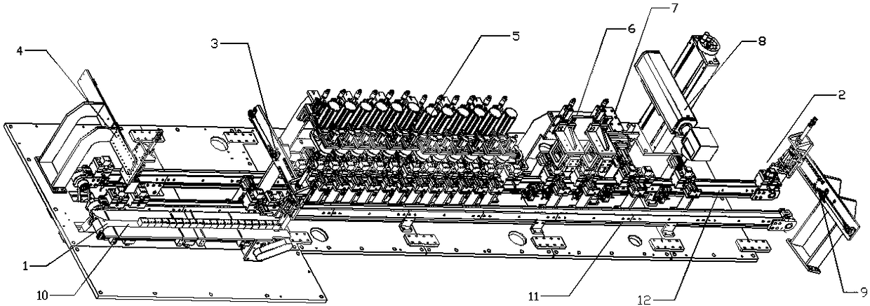
[0054] An automatic processing and production device for transformers includes a shaping section and a testing section.

[0055] The shaping section includes a first transmission mechanism, a first transfer mechanism, a foot cutting mechanism 5 , a foot trimming mechanism 6 , an overturning mechanism 7 and a coding mechanism 8 .

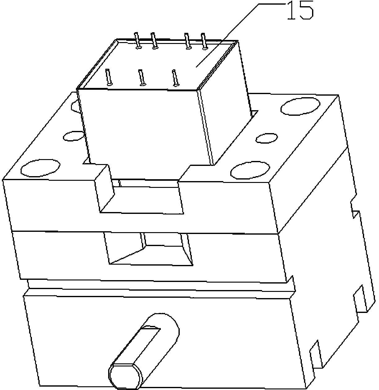
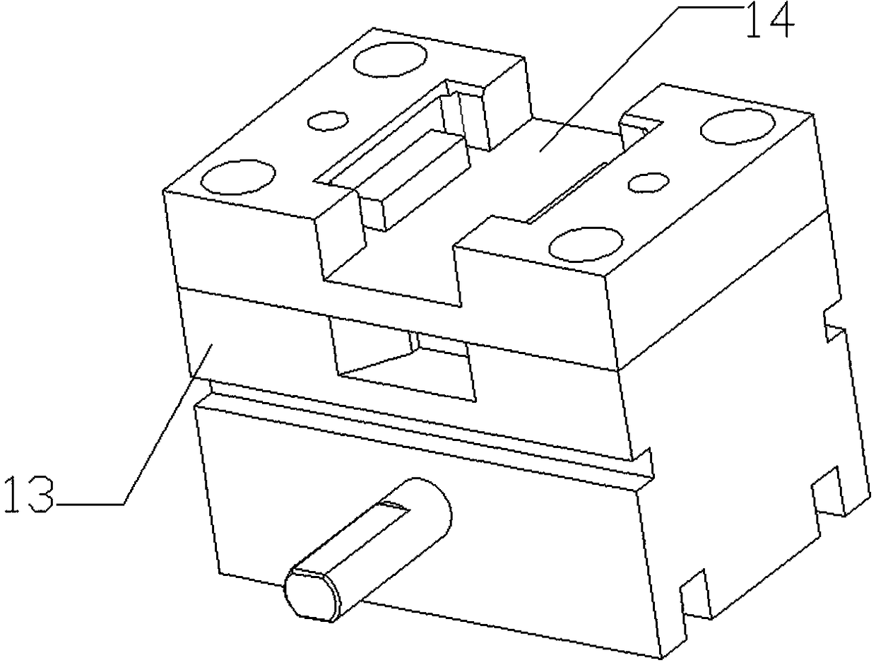
[0056] The first conveying mechanism comprises a transformer bracket 13, a first entrance 1, a first conveyor belt 10, a second conveyor belt 11, a third conveyor belt 12 and a first outlet 2; the transformer 15 is placed on the upper part of the transformer bracket 13 in slot 14. The first conveyor belt 10, the second conveyor belt 11 and the third conveyor belt 12 are parallel to each other. The first inlet 1 is located at the front end of the first conveyor belt 10 , and the first outlet 2 is located at the end of the third conveyor belt 12 .

[0057] The first transfer mechanism includes a first manipulator 3 , a second manipulator 4 and a thir...

Embodiment 2

[0070] The difference between this embodiment and Embodiment 1 is that the first manipulator 3 includes a bracket 21 , a horizontal rail 22 , a vertical rail 23 and a small clamp 25 . Both the second manipulator 4 and the third manipulator 9 include a bracket 21 , a horizontal rail 22 , a vertical rail 23 and a large clamp 24 . The sixth manipulator 45 includes a support 21 , a horizontal rail 22 , a vertical rail 23 and a large clamp 24 . Both the fourth manipulator 43 and the fifth manipulator 44 include a bracket 21 , a horizontal rail 22 , a vertical rail 23 and a small clamp 25 . The seventh manipulator 35 includes a bracket 21 , a horizontal rail 22 , a vertical rail 23 and a small clamp 25 .

Embodiment 3

[0072] The difference between this embodiment and Embodiment 1 is that: the foot-cutting mechanism 5 includes several foot-cutting units, and the foot-cutting units include a foot-cutting motor 16 and a foot-cutting cutter 17 . The foot-shearing mechanism 5 includes a front-section foot-shearing unit and a rear-section foot-shearing unit. The front-section foot-shearing unit and the rear-section foot-shearing unit are on two parallel lines, and the distance between them is the distance between two rows of wires of the transformer 15 .


PUM


Abstract

The invention discloses a transformer automatic machining production device. The transformer automatic machining production device comprises a first conveying mechanism, a first transferring mechanism, a foot shearing mechanism, a foot shaping mechanism, an overturning mechanism and a code printing mechanism, and further comprises a second conveying mechanism, a second transferring mechanism, a primary detection mechanism, a control system, a secondary detection mechanism and a sorting mechanism; according to the transformer automatic machining production device, the process of shaping, detection and sorting are combined into the production device, so that integration automation of shaping, detection and sorting is achieved, manual operation is omitted, full-automatic continuous productionis achieved, detection accuracy is improved, the shaping efficiency and the sorting efficiency are greatly improved, and the processing efficiency of the transformer is improved.

Description

technical field [0001] The invention relates to the technical field of electrical component processing, in particular to an automatic processing and production device for transformers. Background technique [0002] Transformers can be divided into: power transformers and special transformers (electric furnace transformers, rectifier transformers, power frequency test transformers, voltage regulators, mining transformers, audio transformers, intermediate frequency transformers, high frequency transformers, impact transformers, instrument transformers, electronic Transformers, reactors, transformers, etc.). [0003] High-frequency transformer is a power transformer whose working frequency exceeds intermediate frequency (10kHz). It is mainly used as high-frequency switching power transformer in high-frequency switching power supply, and also used as high-frequency inverter in high-frequency inverter power supply and high-frequency inverter welding machine. power transformer. ...

Claims


Application Information

Patent Timeline
Patent Type & Authority Applications(China)
IPC IPC(8): H01F41/00
CPCH01F41/00
Inventor 杨雪芹
Owner SHENZHEN LANSITENG TECH
Why Eureka
Try Eureka