Motor control method for predicting voltage vector sequence
A technology of voltage vector and motor control, which is applied in the fields of power electronic control, permanent magnet synchronous motor control, motor speed regulation, and motor control. The effect of reducing the number of sorting, improving computing efficiency, and reducing motor loss
- Summary
- Abstract
- Description
- Claims
- Application Information
AI Technical Summary
Problems solved by technology
Method used
Image
Examples
Embodiment 1
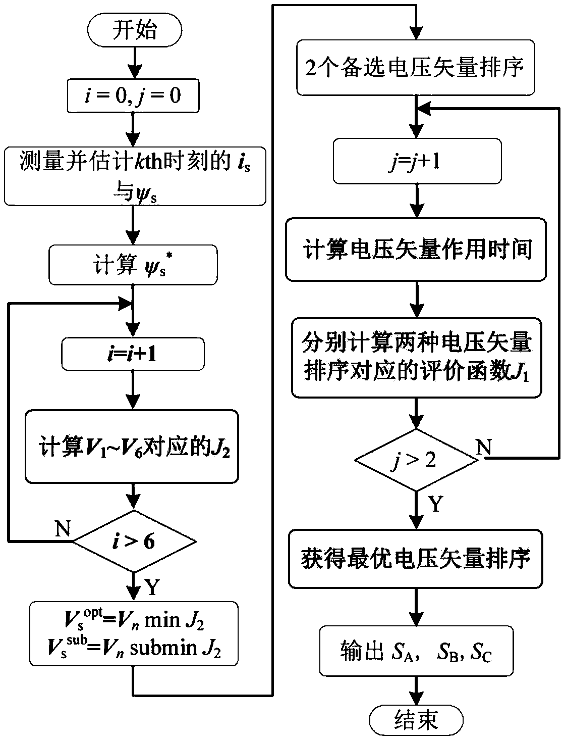
[0048] A motor control method for predicting voltage vector sequences, seefigure 1 , the method includes the following steps:
[0049] 101: Through quantitative analysis of the influence of all voltage vector sorting in the two-level voltage source inverter on the fluctuation of the stator flux vector, all voltage vector sorts that are conducive to optimizing the control performance of the stator flux vector are screened out;
[0050] 102: Incorporate all voltage vector sorting into the control set of predictive control, and establish a new voltage vector sequence control set; use the effective value of the fluctuation amount of the stator flux vector in one control cycle as the evaluation index;
[0051] 103: Evaluate the stator flux vector error at each voltage vector switching moment in each control cycle, and construct an evaluation function;
[0052] 104: Calculate the action time of each basic voltage vector through the two-step method of first confirming the phase angle...
Embodiment 2
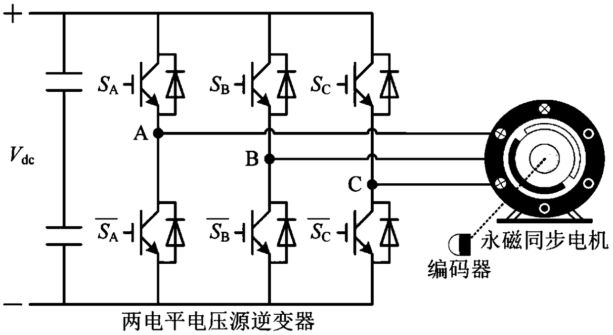
[0055] Combine below Figure 2-Figure 7 1. The specific calculation formula further introduces the scheme in Embodiment 1, see the following description for details:
[0056] 1. Establish the mathematical model of permanent magnet synchronous motor:
[0057] exist figure 2 In the two-level voltage source inverter, the switching states of the upper and lower arm IGBTs are complementary, so the S A , S B and S C Respectively represent the switching states of the upper and lower arm IGBTs of the three-phase (A, B, and C) level voltage source inverter, and "1" indicates that the upper arm IGBT is in the on state and the lower arm IGBT is in the off state , "0" indicates that the upper bridge arm IGBT is in the off state, and the lower bridge arm IGBT is in the on state.
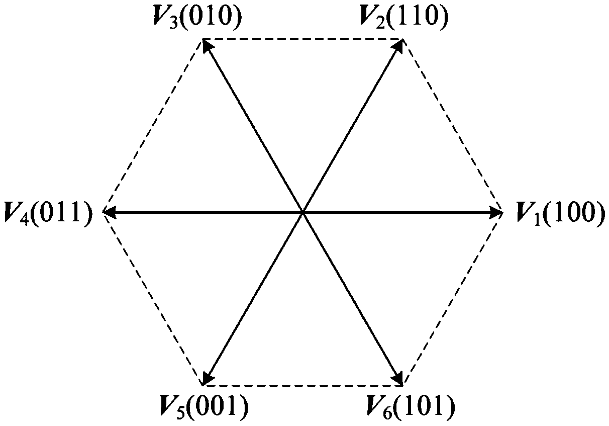
[0058] There are 8 switch combinations in the level voltage source inverter, and the output phase voltages corresponding to these 8 switch combinations are converted into space vector form, and 6 effective ...
Embodiment 3
[0149] Combined with the specific experimental data, Figure 8-Figure 10 , and the simulation waveforms are used to verify the feasibility of the schemes in Examples 1 and 2, see the following description for details:
[0150] The embodiment of the present invention is verified experimentally in a 6.0kW permanent magnet synchronous motor system. The motor parameters are shown in Table 3. In the experimental test platform, the digital signal processor (DSP) TMS320F28335 implements the algorithm, and the load is provided by an induction motor of 11.2kW, and the induction motor is controlled by S120 produced by Siemens.
[0151] table 3
[0152]
[0153] 1. Transient performance verification
[0154] Figure 8 The experimental waveform of the transient performance of the algorithm proposed by the example of the present invention is given. During the experiment, the motor speed was 100r / min, and the load was 50Nm. Then, the given speed of the motor suddenly changed to 200r...
PUM
 Abstract
Description
Claims
Application Information
 - R&D
- Intellectual Property
- Life Sciences
- Materials
- Tech Scout
- Unparalleled Data Quality
- Higher Quality Content
- 60% Fewer Hallucinations
Browse by: Latest US Patents, China's latest patents, Technical Efficacy Thesaurus, Application Domain, Technology Topic, Popular Technical Reports.
© 2025 PatSnap. All rights reserved.Legal|Privacy policy|Modern Slavery Act Transparency Statement|Sitemap|About US| Contact US: help@patsnap.com


