
Helical milling device and helical milling method

A helical milling hole and shaft adjustment technology, which is applied to milling machine equipment, milling machine equipment details, metal processing equipment, etc., can solve the problems of poor rotation consistency between the eccentric adjustment shaft and the revolution shaft, low adjustment accuracy, error accumulation, etc., to achieve improved consistency Performance and stability, improve milling accuracy, and reduce weight

Pending Publication Date: 2018-12-04
NAT INST CORP OF ADDITIVE MFG XIAN
View PDF4 Cites 13 Cited by
  • Summary
  • Abstract
  • Description
  • Claims
  • Application Information

AI Technical Summary

Problems solved by technology

[0010] In order to effectively solve the problem that the existing helical milling device is large in size and mass, resulting in excessive load on the joint arm robot and the end of the machine tool, and at the same time, the adjustment accuracy of the rotation angle of the eccentric adjustment axis is low, and the rotation consistency between the eccentric adjustment axis and the revolution axis is poor. The problem of accumulation of errors caused by the nesting of layer standard bearings, the invention provides a device and method for making helical milling holes

Method used


Image

  • Helical milling device and helical milling method
  • Helical milling device and helical milling method
  • Helical milling device and helical milling method

Examples


Embodiment Construction

[0040] The present invention will be further described below in conjunction with the accompanying drawings and specific embodiments.

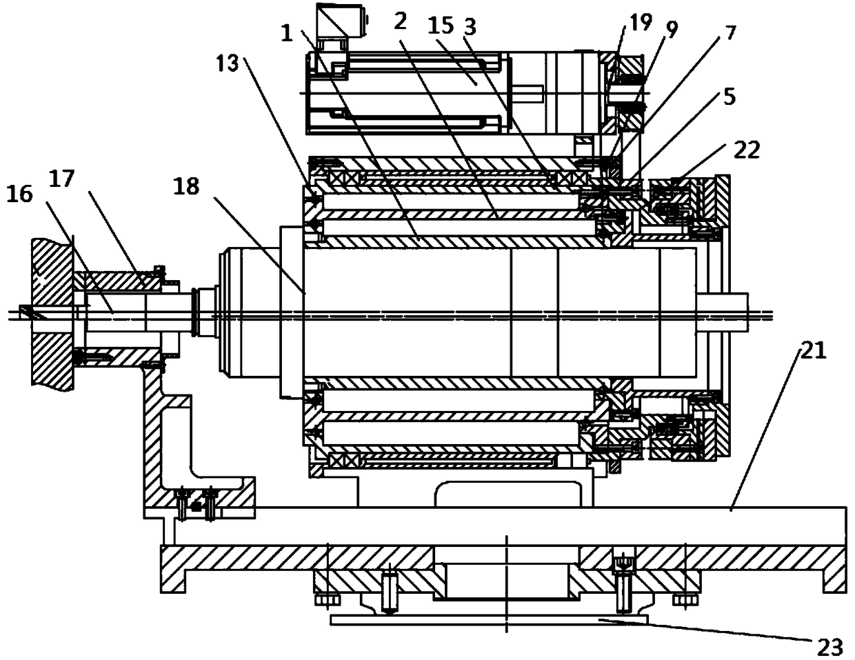
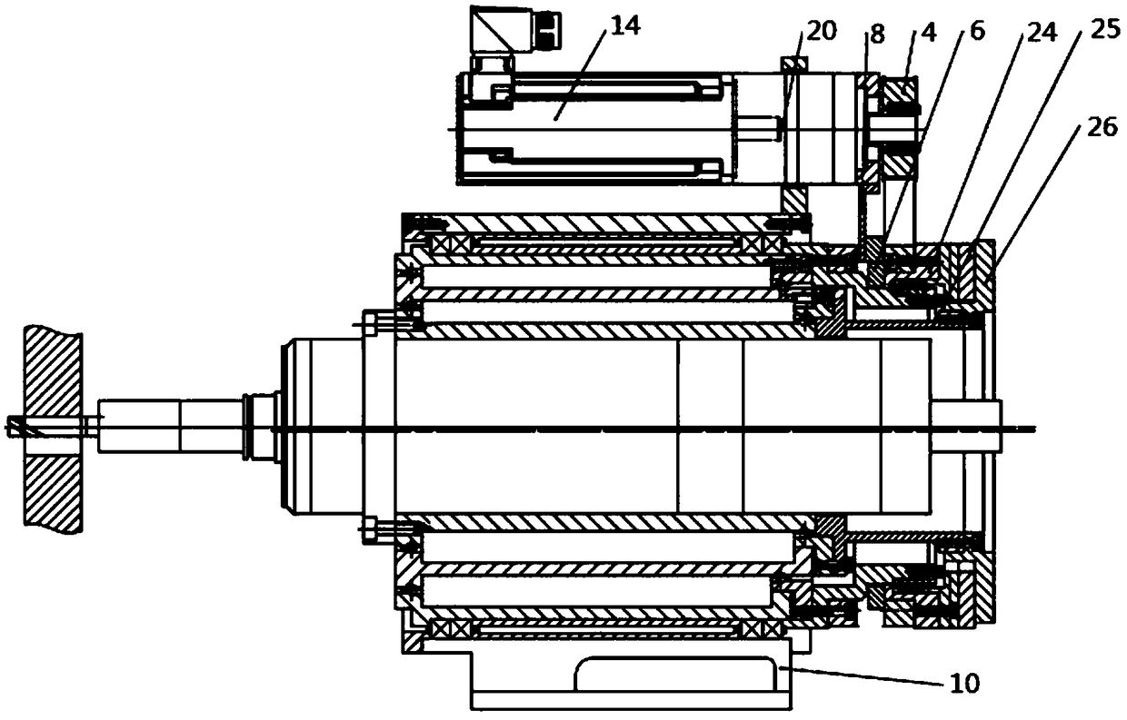
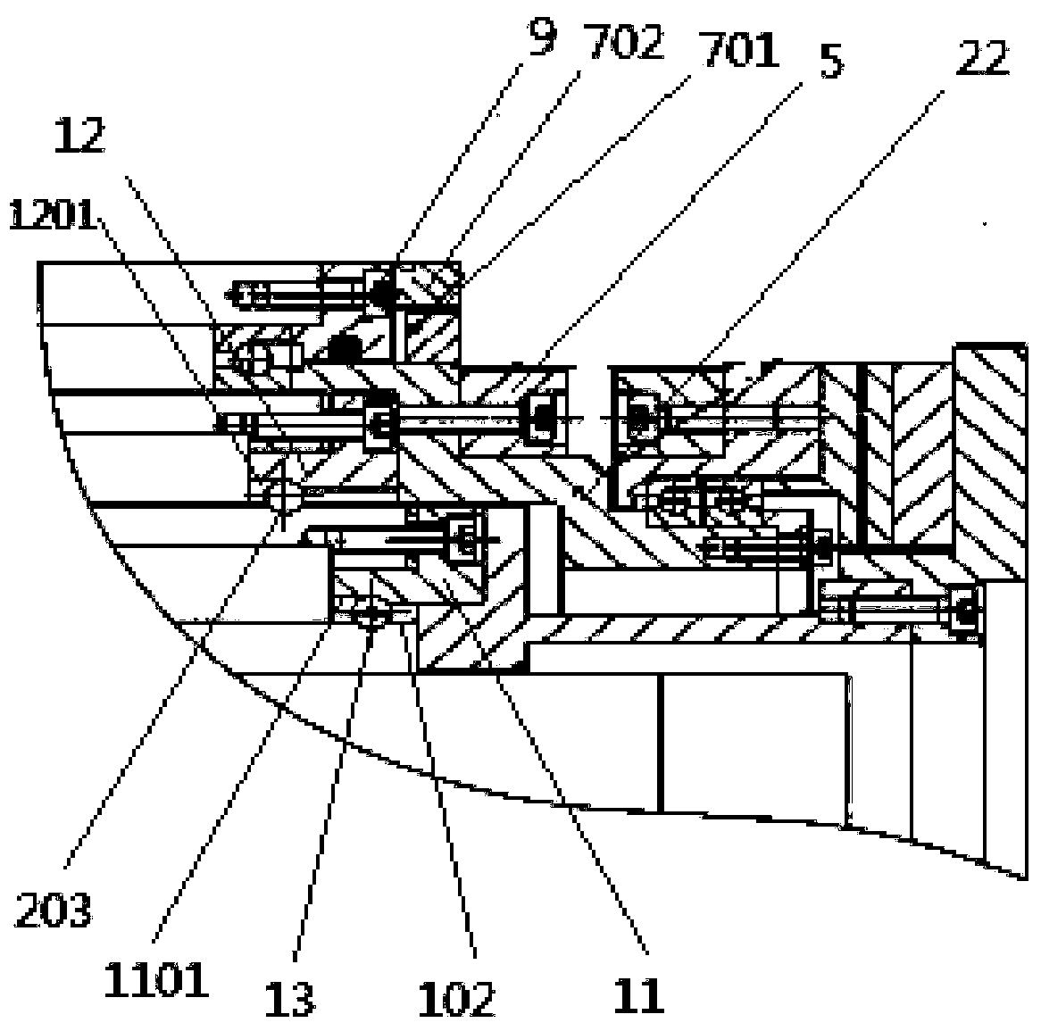
[0041] refer to figure 1 and figure 2 , a spiral milling device comprising: cutter 16, presser foot 17, electric spindle 18, rotation shaft 1, eccentric adjustment shaft 2, revolution shaft 3, revolution motor 15, first planetary reducer 19, revolution pulley 5, adjustment The motor 14 , the second planetary reducer 20 , the adjustment pulley 4 , the support housing 10 , the feed system 21 and the control system also include the adjustment axis detection grating scale 6 and the revolution axis detection grating scale 7 .

[0042] The presser foot 17 presses the workpiece, the tool 16 is installed on the front end of the electric spindle 18, and the outside of the electric spindle 18 is sequentially fitted with the rotation axis 1, the eccentric adjustment axis 2, and the revolution axis 3, wherein the rotation axis 1 is fixed to the electric ...


PUM


Abstract

The invention belongs to the technical field of automatic hole production, and concretely relates to a helical milling device and a helical milling method. The helical milling device comprises an autorotation shaft, an eccentric adjusting shaft, a revolution shaft, a revolution belt pulley, an adjusting belt pulley and a control system, and further comprises an adjusting shaft detection grating ruler and a revolution shaft detection grating ruler, and full-closed loop detection is performed on the rotation angle of the eccentric adjusting shaft and the synchronization of the revolution shaft and the eccentric shaft. The revolution shaft, the eccentric adjusting shaft and the autorotation shaft of the device are provided with raceways, rolling elements are clamped in the raceways, and the self race ways and the rolling elements are adopted to substitute standard bearings, so problems of low rotating angle adjusting precision of existing helical milling devices and poor rotating consistence of the eccentric adjusting shaft and the autorotation shaft, and problems of overlarge use load of a hinged arm robot and a machine tool end and error accumulation caused by nesting of multilayerstandard bearings, caused by large size and large mass of the device are solved.

Description

technical field [0001] The invention relates to the technical field of automatic hole making, in particular to a helical hole milling device and method. Background technique [0002] One generation of materials and one generation of equipment, with the increasing use of high-end materials such as composite materials and titanium alloys in the fields of aviation, aerospace, transportation and other high-end equipment manufacturing, composite materials, difficult-to-process materials and their composites will follow. High-efficiency and high-precision machining requirements for high-precision assembly holes in high-end equipment manufacturing applications. As an emerging hole processing technology, helical milling holes are replacing traditional drilling processes to meet the high-efficiency and high-precision holes in high-end equipment. processing needs. [0003] The focus of the application of the helical milling process is to develop a special helical milling device to re...

Claims


Application Information

Patent Timeline
IPC IPC(8): B23C3/00B23C9/00
CPCB23C3/00B23C9/00B23C2220/52
Inventor 汤永凯王磊盛晓东王俊玲卢秉恒赵纪元
Owner NAT INST CORP OF ADDITIVE MFG XIAN
Learn More