Side-stream type end-tidal carbon dioxide detecting device

A carbon dioxide detection device technology, which is applied in the fields of blood characterization device, diagnostic recording/measurement, medical science, etc., can solve the problems of inconvenient insertion and removal of catheters, affecting the detection effect, and the catheter is easy to fall off, and achieves simple use, small size, simple structure

Pending Publication Date: 2018-12-07
苏州创莱电子科技有限公司
View PDF3 Cites 3 Cited by
  • Summary
  • Abstract
  • Description
  • Claims
  • Application Information

AI Technical Summary

Problems solved by technology

[0007] The purpose of the present invention is to provide a side-flow type end-tidal carbon dioxide detection device to solve the problems in the prior art that the volume is large, the catheter is easy to fall off during use, and the insertion and removal of the catheter is inconvenient to use, which affects the detection effect.

Method used


Image

  • Side-stream type end-tidal carbon dioxide detecting device
  • Side-stream type end-tidal carbon dioxide detecting device
  • Side-stream type end-tidal carbon dioxide detecting device

Examples


Embodiment 1

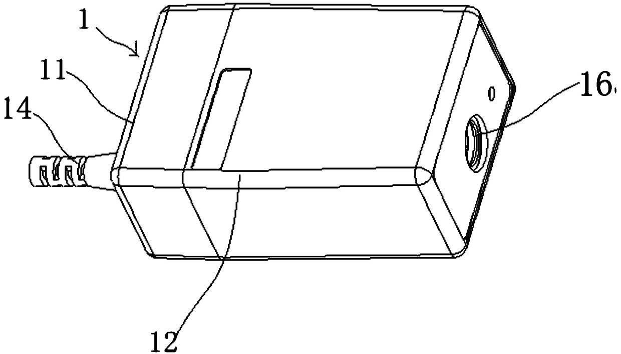
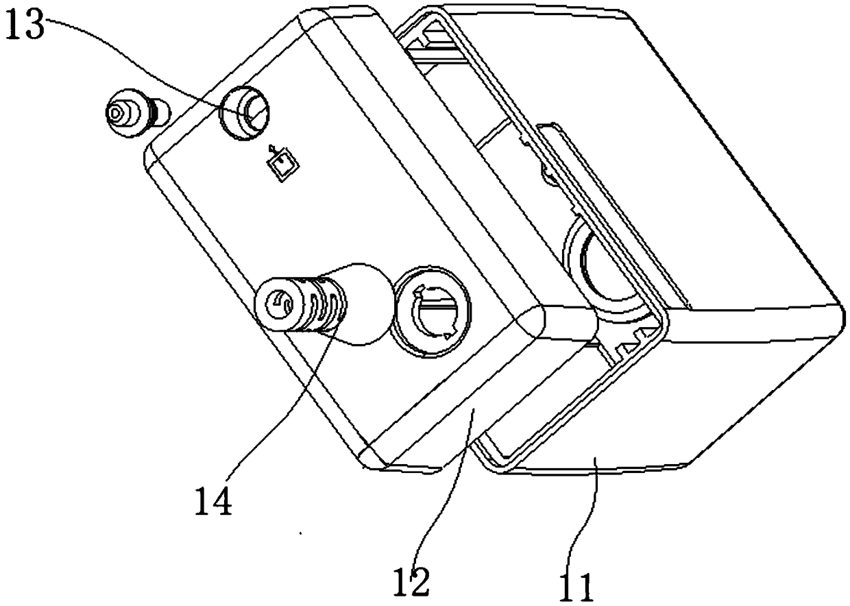
[0035] Embodiment 1: as figure 1 As shown, a side-flow end-tidal carbon dioxide detection device includes a first housing 1, a first connecting terminal 13, a conduit and a first external connector 14, an infrared detector, a detection conduit, an air pump, and a carbon dioxide detection circuit board .

[0036] Wherein, the first casing 1 is assembled by an upper casing 11 and a lower casing 12 , generally in the shape of a cuboid or a cylinder, and the lower casing 12 is arranged at the lower part of the upper casing 11 . The bottom of the lower casing 12 is provided with an airflow hole, and one end of the first connecting end 361 located in the inner conduit of the airflow hole is connected to the side flow branch of the breathing circuit, and the other end is connected to the first outer connector 362 . The first external connector 362 is pluggably connected to the connecting terminal 361 at the bottom of the lower housing 12 . The upper casing 11 also includes an air o...

Embodiment 2

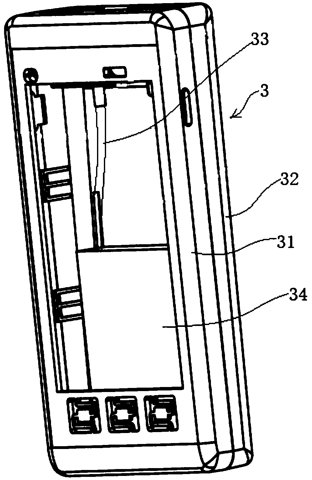
[0039] Embodiment 2: In order to further facilitate the detection of breathing gas and display corresponding data, this embodiment also discloses a hand-held end-tidal carbon dioxide and blood oxygen monitor 3, which replaces the traditional large-scale human breathing detection instrument to achieve handheld use. The purpose is to realize the detection of human metabolism parameters more easily and conveniently through breathing gas, including carbon dioxide detection, blood oxygen detection and so on.

[0040] Such as Figure 4 to Figure 5 As shown, in this embodiment, the side-flow end-tidal carbon dioxide detection device is connected to the hand-held end-tidal carbon dioxide oximeter 3 through a data cable.

[0041] Specifically, the handheld end-tidal carbon dioxide oximeter monitor 3 includes a second housing, a circuit board and a battery 34 . In order to facilitate the introduction of gas, the hand-held end-tidal carbon dioxide oximeter monitor 3 can also be provided...


PUM


Abstract

The invention discloses a side-stream type end-tidal carbon dioxide detecting device. The device comprises a first shell body provided with an airflow hole, a first connecting end head located in thefirst shell body and fixed in the airflow hole, a duct, a first external connecting joint, a detecting duct and an air pump, wherein one end of the duct is communicated with a side-stream branch pathof a breathing loop, the other end of the duct is connected with the first external connecting joint, and the first external connecting joint is in plug connection with the first connecting end head;an infrared detector is arranged in the first shell body and comprises an emitter and a receiver; one end of the detecting duct is connected with the first connecting end head and located between theemitter and the receiver; the air pump is communicated with the detecting duct. The side-stream type end-tidal carbon dioxide detecting device is simple in structure, smaller in size and convenient tocarry and use, in the using process, the side-stream type end-tidal carbon dioxide detecting device and a hand-hold end-tidal carbon dioxide monitor can be used as a set, and the problem that in theusing process, the detecting effect is poorer due to the fact that the duct is separated from the device is solved.

Description

technical field [0001] The invention relates to the fields of health testing equipment, medical equipment, etc., and specifically relates to a side-flow end-tidal carbon dioxide detection device, which mainly detects the content of carbon dioxide and other gases in breathing gas. Background technique [0002] The PetCO2 monitor is based on the principle that CO2 gas only has a strong absorption effect on infrared rays with a wavelength of 4.26 μm. When the infrared rays emitted by the sensor pass through the gas sampling chamber in the middle, the CO2 gas flowing through the chamber absorbs part of the infrared energy. After processing by the microcomputer, the PetCO2 waveform and value are displayed. The normal value of PetCO2 is 35-45mmHg. 2. PETCO2 waveform and its significance 2.1 A normal CO2 waveform can generally be divided into four phases and four segments: (1) Phase I: Inspiratory baseline, which should be at zero, is the beginning of exhalation, which is the dead ...

Claims


Application Information

Patent Timeline
Patent Type & Authority Applications(China)
IPC IPC(8): A61B5/083A61B5/145
CPCA61B5/0836A61B5/14542A61B5/4866
Inventor 许天罡
Owner 苏州创莱电子科技有限公司
Why Eureka
Try Eureka