Novel dialysis tube used for hemodialysis equipment

A hemodialysis and dialysis tube technology, applied in the field of new dialysis tubes, can solve the problems of slow dialysis efficiency, increase in medical waste, and slow dialysis efficiency, and achieve the effect of heating up, simple overall structure, and avoiding discomfort.

Inactive Publication Date: 2018-12-07
CHENGDU GUANYU TECH
View PDF7 Cites 4 Cited by
  • Summary
  • Abstract
  • Description
  • Claims
  • Application Information

AI Technical Summary

Problems solved by technology

[0004] (1) Existing dialysis equipment is relatively large in size and is only configured in the hospital. If the patient wants to perform hemodialysis, he can only go to the hospital. For patients who need long-term hemodialysis, this brings the patient It is a big trouble, requiring patients to go to the hospital regularly, which increases the patient's burden of illness, and also requires specialized medical staff to operate hemodialysis equipment during dialysis operations, which will also increase the workload of medical staff;
[0005] (2) The dialysis membrane in the dialysis equipment is an indispensable component to realize the dialysis function. The existing dialysis equipment only includes a dialysis membrane with a hollow structure inside. When the dialysis operation is performed, the efficiency of the dialysis is relatively slow, which will It brings more pain to the patient, and if the patient's blood is drawn too much at one time, and the dialysis efficiency is very slow, it is easy to ca

Method used


Image

  • Novel dialysis tube used for hemodialysis equipment
  • Novel dialysis tube used for hemodialysis equipment
  • Novel dialysis tube used for hemodialysis equipment

Examples


Embodiment Construction

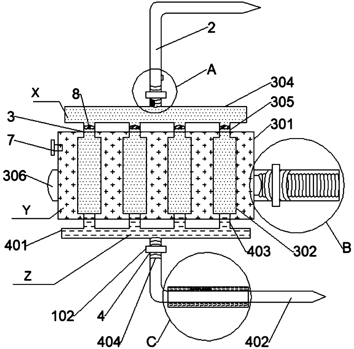
[0042] Such as Figure 1 to Figure 7As shown, the present invention provides a new type of dialysis tubing for hemodialysis equipment, including a dialysis control device 1 and a dialysis needle tube 2 for drawing blood from the patient's body. When performing dialysis operations, the dialysis needle tube 2 is inserted into the patient's artery Inside, one end of the dialysis needle tube 2 is provided with a hemodialysis device 3, and the hemodialysis device 3 is respectively connected with a blood return device 4 for retransporting the dialysis-purified blood to the patient's body and a blood return device 4 for separating and discharging the blood after dialysis to produce dialysis. Mass liquid sorting mechanism 5 of waste.

[0043] The hemodialysis device 3 includes a dialysis bag 301 filled with dialysate and several fibrous dialysis membranes 302 in a tubular structure, the fibrous dialysis membranes 302 are arranged in the dialysis bag 301, and the arrangement of a plura...


PUM


Abstract

The invention discloses a novel dialysis tube used for hemodialysis equipment. The novel dialysis tube comprises a dialysis control device and a dialysis needle tube used for leading out blood in thebody of a patient. A hemodialysis device is arranged at one end of the dialysis needle tube and connected with a blood reflux unit and a substitution fluid separating and discharging mechanism, wherein the blood reflux unit is used for conveying the blood Z after dialysis and purification back into the body of the patient, and the substitution fluid separating and discharging mechanism is used forseparating and discharging dialysis waste generated after dialysis, the blood is drawn from the body of the patient through the dialysis needle tube, then the function of dialysis is realized under the effect of the blood dialysis device, the blood Z after dialysis and purification is conveyed back into the body of the patient through the blood reflux unit, and meanwhile through the substitutionfluid separating and discharging mechanism, the waste generated by dialysis is discharged. The novel dialysis tube is simple in structure, easy and convenient to operate and capable of efficiently andrapidly dialyzing the blood of the patient, in this way, pains of the patient during blood dialysis are reduced, and the safe reliability of the whole process of dialysis is guaranteed.

Description

technical field [0001] The invention relates to the technical field of medical equipment, in particular to a novel dialysis tube used in hemodialysis equipment. Background technique [0002] Hemodialysis is one of the renal replacement therapy methods for patients with acute and chronic renal failure. It drains the blood in the body to a dialyzer outside the body. The principle of ultrafiltration and convection exchanges substances, eliminates metabolic waste in the body, maintains electrolyte and acid-base balance; at the same time removes excess water in the body, and the whole process of returning purified blood is called hemodialysis. [0003] Hospitals use specialized hemodialysis equipment when performing hemodialysis on patients. The following problems often exist in the use of existing hospital hemodialysis equipment: [0004] (1) Existing dialysis equipment is relatively large in size and is only configured in the hospital. If the patient wants to perform hemodialy...

Claims


Application Information

Patent Timeline
IPC IPC(8): A61M1/20A61B5/145A61M1/36
CPCA61B5/14528A61M1/16A61M1/1623A61M1/1654A61M1/1692A61M1/369A61M2230/20
Inventor 赵洪珍
Owner CHENGDU GUANYU TECH
Why Eureka
Try Eureka