
Waste material collection device for machining of guide rod of road marker

A waste collection and guide rod technology, which is applied in metal processing equipment, metal processing machinery parts, manufacturing tools, etc., can solve problems affecting waste collection and blockage, and achieve the effect of reducing labor intensity, avoiding pollution, and improving service life.

Inactive Publication Date: 2018-12-07
CHANGXING QIKAI MECHANICAL EQUIP CO LTD
View PDF0 Cites 1 Cited by
  • Summary
  • Abstract
  • Description
  • Claims
  • Application Information

AI Technical Summary

Problems solved by technology

[0004] The purpose of the present invention is to solve the shortcomings of the prior art that cause blockage during use and affect the collection of waste materials, and propose a waste material collection device for processing guide rods of marking machines

Method used


Image

  • Waste material collection device for machining of guide rod of road marker
  • Waste material collection device for machining of guide rod of road marker
  • Waste material collection device for machining of guide rod of road marker

Examples


Embodiment 1

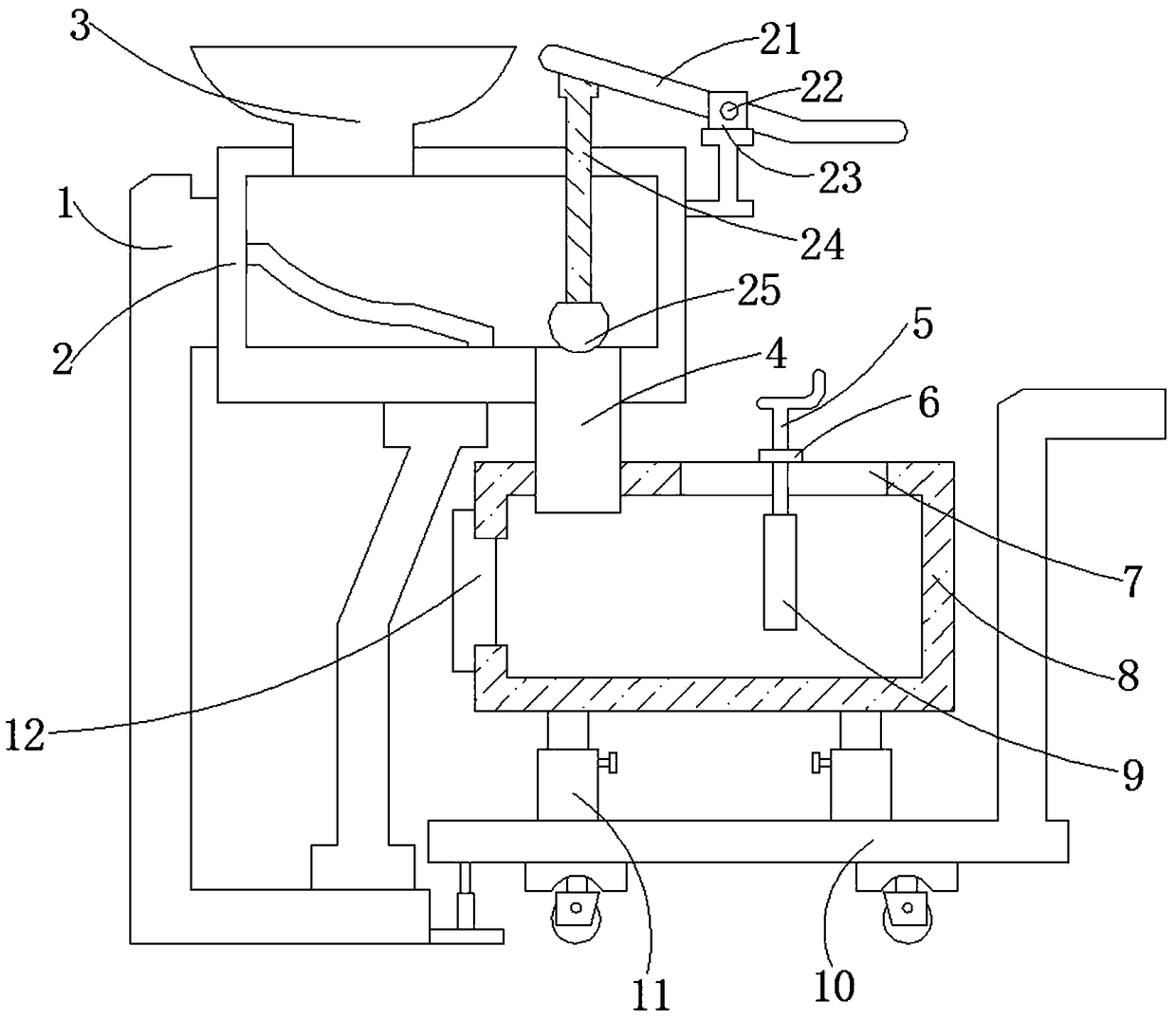
[0023] Embodiment 1: When using the collection device to collect the waste generated by the processing of the guide rod, it is necessary to place the entire device on the lower side of the processing device close to the guide rod, so that the waste generated during the processing passes through the feed channel 3 , transported to the inside of the collection box 2, and under the action of the guide plate provided in the collection box 2, the waste falling into the collection box 2 can slide down to the inside of the delivery channel 4, and through the transmission of the delivery channel 4, it can Let the waste fall into the interior of the recovery box 8, and collect the waste generated during the processing of the guide rod, which avoids the pollution of the processing environment caused by the waste generated during the processing, and also saves the time for manual cleaning of the waste, and reduces the waste disposal. labor intensity.

Embodiment 2

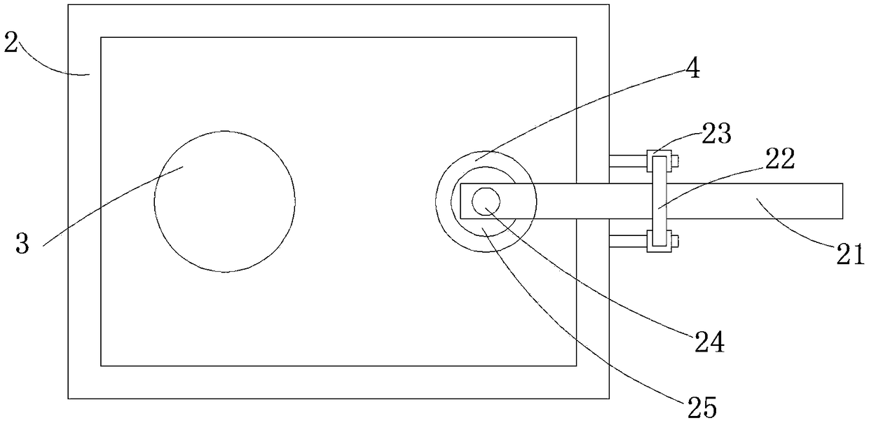
[0024] Embodiment 2: In the process that the waste material generated by the guide rod processing continuously falls into the collection box 2, the waste material blockage may occur in the conveying channel 4. At this time, the first connecting rod 21 is manually held, and the first connecting rod 21 is wound The fixed rod 22 pushes up and down, and when the first connecting rod 21 is pushed, it will drive the second connecting rod 24 to move up and down in the collection box 2, and the piston block 25 moves up and down in the conveying channel 4. The conveying movement in the direction pushes the waste materials near the conveying channel 4, avoiding the clogging phenomenon when the conveying channel 4 transports waste materials, and improving the service life of the waste material collecting device.

Embodiment 3

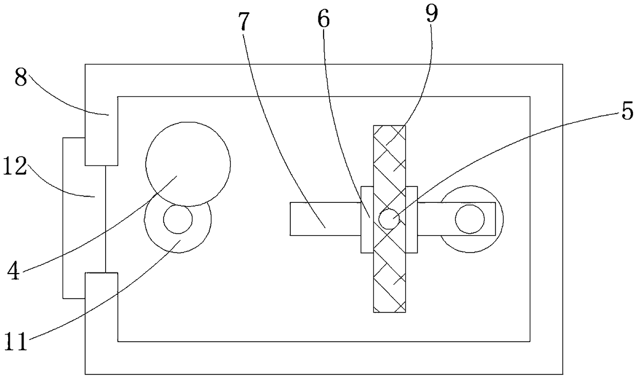
[0025] Embodiment 3: When the amount of waste collected in the recovery box 8 is gradually increasing, the movable push rod 5 can be manually held at this time, so that the movable push rod 5 can pull the linkage push plate 9, so that the position of the linkage push plate 9 can be adjusted. Increase the height, and hold the movable push rod 5 to make the interlocking push plate 9 obliquely set, and the interlocking push plate 9 will obliquely scrape the waste near the side of the conveying channel 4 to the side away from the conveying channel 4. The push plate 9 stacks waste materials in the recovery box 8, which improves the utilization rate of the space in the recovery box 8.


PUM


Abstract

The invention discloses a waste material collection device for machining of a guide rod of a road marker. The waste material collection device for machining of the guide rod of the road marker comprises a fixing frame, a collection box and a recycling box. The waste material collection device is characterized in that the collection box is arranged on the side wall of one end of the fixing frame; athrough hole is formed in a side wall of the bottom end of the collection box, and a transportation channel is arranged at the bottom end of the collection box; one end of the transportation channelis movably connected to the interior of the recycling box in a clamped manner. A rectangular through hole is formed in a side wall of the upper end of the recycling box, and a limiting block is arranged inside the rectangular through hole. A movable push rod is arranged in the interior of the limiting block. The waste material falling into the collection box slides to the interior of the transportation channel. Through transferring of the transportation channel, the waste material falls into the interior of the recycling box. Waste material produced in the machining process of the guide rod iscollected; pollution caused to the machining environment by the waste material produced in the machining process is avoided; time spent on hand sweeping of the waste material is also saved; and laborintensity of waste material treatment is lowered.

Description

technical field [0001] The invention relates to the technical field of mechanical processing, in particular to a waste material collection device for processing guide rods of marking machines. Background technique [0002] Marking machine, a road construction machine that is widely used in roads, parking lots, squares and runways to draw different restrictions, guidelines and warnings on the flat ground. With its fast, efficient, accurate and other advantages, the marking machine has played a huge role in urban planning and road construction, saving the construction period and economic investment of road construction to the greatest extent. The guide rod is an integral part of the marking machine. [0003] When the existing guide rods of the marking machine are mechanically processed, the waste generated directly falls on the lower end of the processing machine. After the processing is completed, the staff will clean them up. Most of them are not equipped with waste collect...

Claims


Application Information

Patent Timeline
IPC IPC(8): B23Q11/00
CPCB23Q11/00
Inventor 许胜强
Owner CHANGXING QIKAI MECHANICAL EQUIP CO LTD
Learn More