
Bottle cap feeding and assembling device

An assembly device and material feeding technology, which is applied in the field of bottle and can processing, can solve problems such as unfavorable assembly, short service life of springs, and large tension changes, and achieve the effects of avoiding accidents, facilitating subsequent processing, and precise rotation angles

Inactive Publication Date: 2018-12-07
徐晓伟
View PDF0 Cites 1 Cited by
  • Summary
  • Abstract
  • Description
  • Claims
  • Application Information

AI Technical Summary

Problems solved by technology

No matter what kind of material the bottle needs to be used with the bottle cap, in production, the feeding of the bottle cap is usually realized by a feeder. Common feeders include vibration type, centrifugal rotation type, etc., but these feeders The feeding uniformity and stability of the bottle caps are poor, and the feeding caps are not conducive to direct assembly with the bottle
At present, there are also a small number of linear feeding devices on the market. The spring is used as the driving force source for the empty travel of the feeding slider. The deformation of the spring is equal to the stroke of the feeding slider. The tension in the spring changes greatly, and the service life of the spring is longer Short, not conducive to long-term continuous operation of equipment
Moreover, in common production, the connection between material supply and assembly is relatively poor, which seriously affects production efficiency

Method used


Image

  • Bottle cap feeding and assembling device
  • Bottle cap feeding and assembling device

Examples


Embodiment Construction

[0013] The present invention will be further described in detail below in conjunction with the accompanying drawings and examples. The following examples are explanations of the present invention and the present invention is not limited to the following examples.

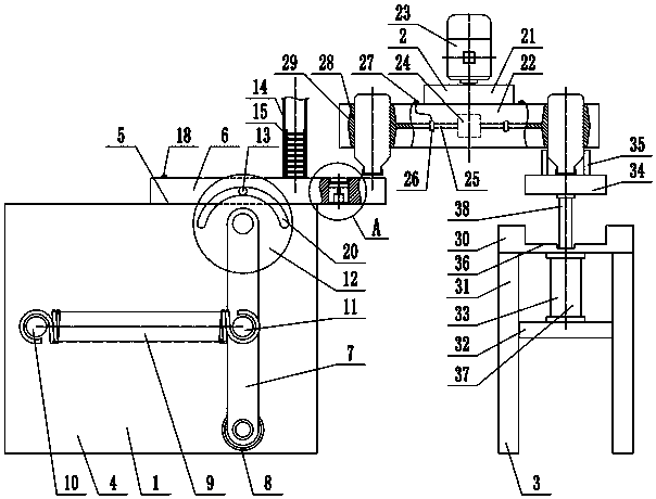
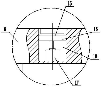
[0014] Such as figure 1 and figure 2 As shown, a bottle cap feeding assembly device includes a feeding mechanism 1, a rotary assembly mechanism 2, and a feeding mechanism 3. The feeding mechanism 1 includes a feeding frame 4, a feeding guide rail 5, and a feeding slide Block 6, swing bar 7, swing cylinder 8, spring 9, spring left pull rod 10, spring right pull rod 11, moving sheave 12, bearing pin 13, feed material channel 14, bottle cap 15, top plate 16, electromagnet 17, Electromagnet button 18, described feeding guide rail 5 is horizontally arranged on the upper side of feeding frame 4, and described feeding slider 6 can slide left and right to be arranged on the feeding guide rail 5, and one of described feedi...


PUM


Abstract

The invention provides a bottle cap feeding and assembling device and belongs to the technical field of bottle and can processing. The bottle cap feeding and assembling device comprises a feeding mechanism, a rotating assembling mechanism and a discharging mechanism; a feeding slider of the feeding mechanism is arranged on a feeding guide rail in a left and right sliding manner; a feeding notch isformed in the right side of a feeding material way; an electromagnet is connected with a top plate; the lower end of a swinging rod is connected with a swinging cylinder; a movable groove wheel is rotationally arranged at the upper end of the swinging rod; a pin shaft installed on the feeding slider is inserted into an arc-shaped groove of the movable groove wheel; the two ends of a spring are connected with a spring left pulling rod and a spring right pulling rod correspondingly; bottle and can clamping grooves are uniformly arranged on a rotating disk of the rotating assembling mechanism; aclamping gas bag is installed in the bottle and can clamping grooves of the rotating disk; the two ends of a gas sucking pipeline are connected with the clamping gas bag and an air compressor correspondingly; the gas sucking pipeline is provided with a gas valve; and the upper end of a discharging piston rod of the discharging mechanism is connected with a discharging bearing frame. The bottle cap feeding and assembling device can achieve feeding and assembling of bottle caps, tensile force of the spring is small in changing, and the service life of the spring is greatly prolonged.

Description

technical field [0001] The invention relates to the technical field of bottle can processing, in particular to a bottle cap feeding and assembling device. Background technique [0002] Bottles and jars are utensils used for holding, which are widely used in various fields of production and life. The current bottle material is mainly plastic, glass and ceramics. Among them, plastic bottles are the most widely used, mainly in medicine, cosmetics, health care products, food, beverages, etc., while glass bottles are mainly used in wine, beverages, and cosmetics. The materials of plastic bottles include PET\PEN\PVC\ABS\PMMA\LDPE, etc. Among them, the prospect of PET is very promising. No matter what kind of material the bottle needs to be used with the bottle cap, in production, the feeding of the bottle cap is usually realized by a feeder. Common feeders include vibration type, centrifugal rotation type, etc., but these feeders The feeding uniformity and stability of the bott...

Claims


Application Information

Patent Timeline
IPC IPC(8): B67B3/02B67B3/06
CPCB67B3/02B67B3/06
Inventor 徐晓伟
Owner 徐晓伟
Learn More