
Single-box multi-chamber box girder bridge and a construction method thereof

A single-box, multi-chamber, box-girder technology, applied in bridges, bridge construction, erection/assembly of bridges, etc., can solve problems such as difficult to guarantee the quality of concrete pouring, longitudinal cracks or honeycomb hemp surface, and small prefabricated box girder space.

Pending Publication Date: 2018-12-07
GUANGZHOU URBAN PLANNING & DESIGN SURVEY RES INST
View PDF5 Cites 7 Cited by
  • Summary
  • Abstract
  • Description
  • Claims
  • Application Information

AI Technical Summary

Problems solved by technology

[0004] (1) Due to the high construction technology requirements of the prefabricated box girder and the closed section structure, it is difficult to guarantee the quality of the concrete pouring of its web and lower flange. When the management and construction control are not in place, it is easy to appear longitudinal crack or honeycomb
[0005] (2) The inner space of the prefabricated small box girder is relatively narrow, and it is relatively troublesome to pour the concrete at one time and remove the inner formwork, and the quality of the concrete in the box is not easy to inspect
[0010] (3) For the construction of cast-in-place box girders, after the preloading of the brackets is completed, the steel bars must be erected on site and the concrete poured, and a certain maintenance period is required before the prestressed tension can be carried out. The construction period is longer than that of prefabricated beams. In the tense project, its construction plan limits the progress of the project

Method used


Image

  • Single-box multi-chamber box girder bridge and a construction method thereof
  • Single-box multi-chamber box girder bridge and a construction method thereof
  • Single-box multi-chamber box girder bridge and a construction method thereof

Examples


Embodiment Construction

[0096] The technical solutions in the embodiments of the present invention will be clearly and completely described below in conjunction with the accompanying drawings in the embodiments of the present invention. Obviously, the described embodiments are only a part of the embodiments of the present invention, rather than all the embodiments. Based on the embodiments of the present invention, all other embodiments obtained by those of ordinary skill in the art without creative work shall fall within the protection scope of the present invention.

[0097] In the description of the present invention, it should be understood that the directions or positional relationships indicated by the terms "upper", "lower", "left", "right", "top", "bottom", etc. are based on the drawings shown The orientation or positional relationship is only for the convenience of describing the present invention and simplifying the description, rather than indicating or implying that the pointed device or elem...


PUM


Abstract

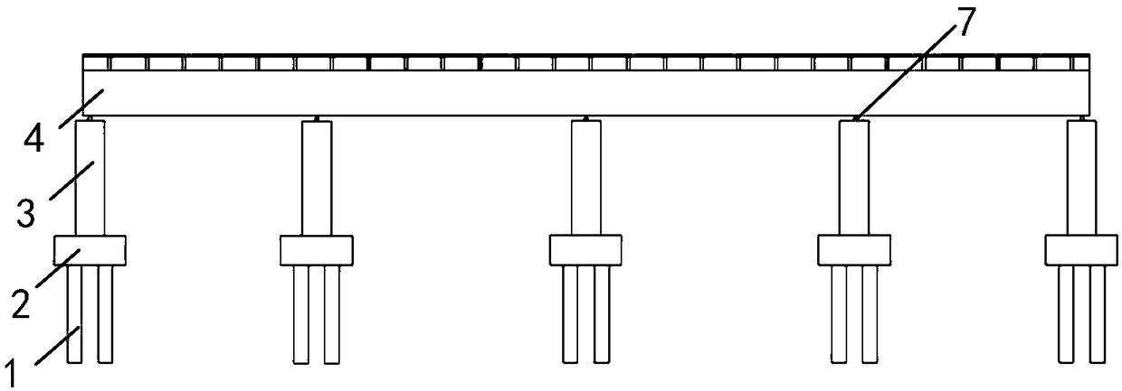
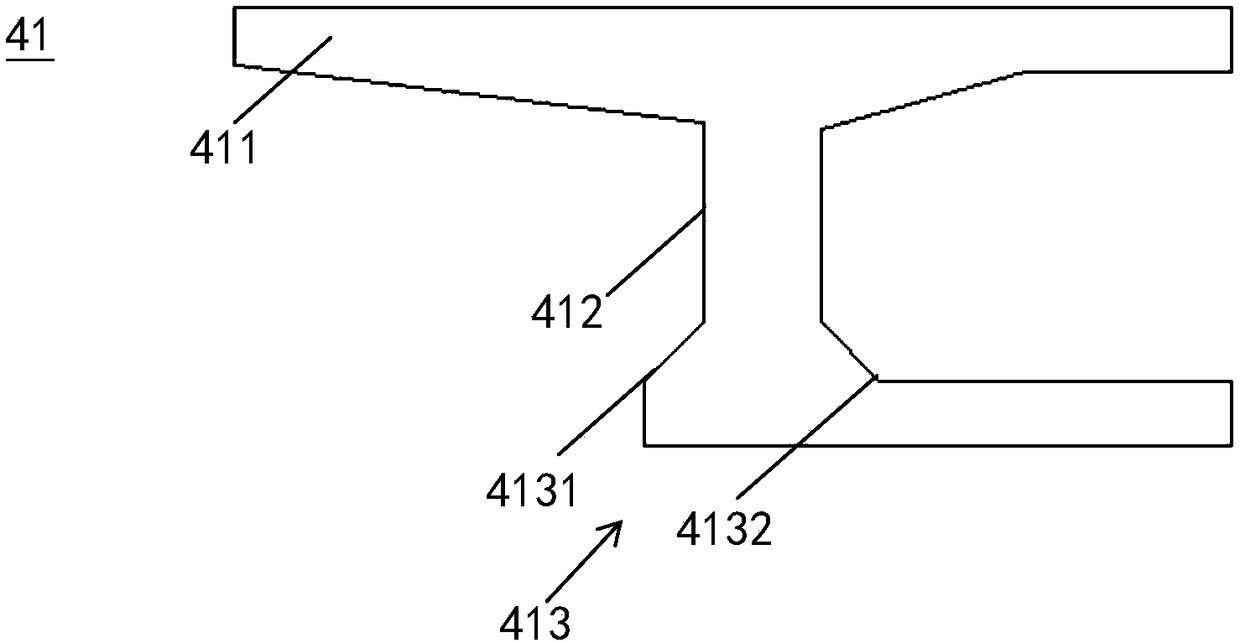
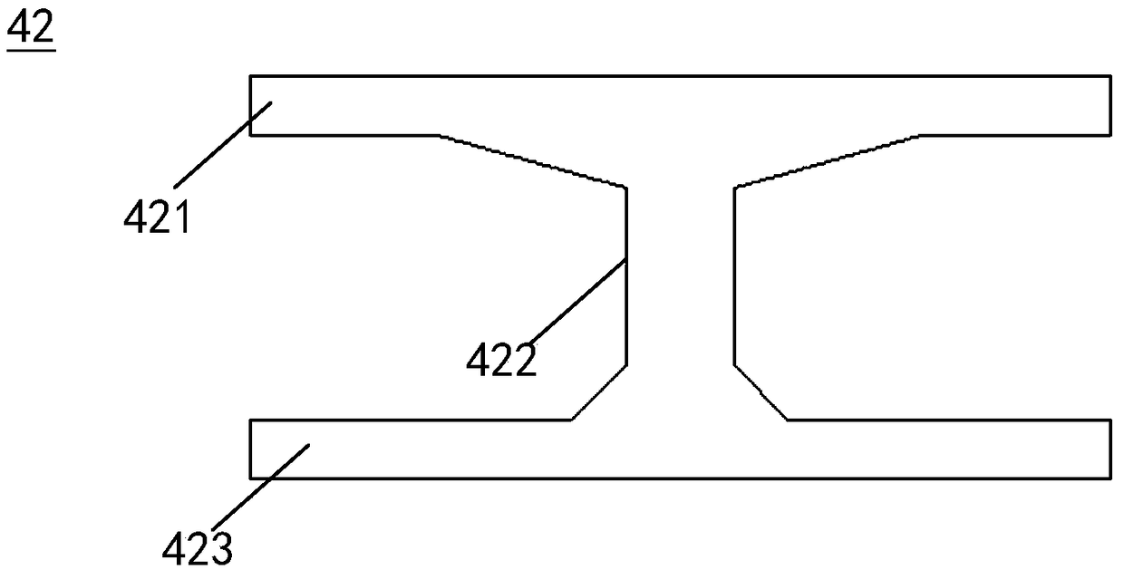
A single-box multi-chamber box girder bridge include that substructure lower structure, single box and multi-chamber box girder, cast-in-place deck, transversely prestressed steel strand, a first longitudinally prestressed steel strand and a second longitudinally prestressed steel strand, Single box multi-chamber box girder includes two precast side beams and a plurality of interconnected precastmiddle beams between the two precast side beams. The precast side beams and the precast middle beams of I-beam structure can reduce the requirements of lifting equipment and the construction cost of single box multi-chamber box girder bridge in the hoisting construction. The first longitudinally prestressed steel strand and the second longitudinally prestressed steel strand improve the mechanicalstate of the middle and lower parts of the prefabricated side beam and the prefabricated middle beam, respectively; Prefabricated side beams and prefabricated middle beams are prefabricated parts, which have the characteristics of high quality concrete, beautiful appearance and light weight. The invention also provides a construction method of a single-box multi-chamber box girder bridge, which can ensure the stability, safety and convenience of the installation of the single-box multi-chamber box girder bridge.

Description

Technical field [0001] The invention relates to the field of building construction engineering, in particular to a single-box multi-chamber box girder bridge and a construction method thereof. Background technique [0002] Box girder structure has certain advantages in bridge construction due to its simple vision and shorter beam height than other types of bridges. Therefore, box girder bridges are widely used in highway bridges, municipal bridges and railway bridges. The existing technology Box girder is mainly divided into prefabricated box girder and cast-in-place box girder. The prefabricated box girder is prefabricated in a separate site and combined with bridge erector or hoisting equipment to be erected after the completion of the lower project. The prefabricated box girder is mostly a single box single room small box girder structure ; The cast-in-place box girder is the erection form of the project site to bind the steel bars and pour concrete. It can be a single-box sin...

Claims


Application Information

Patent Timeline
Patent Type & Authority Applications(China)
IPC IPC(8): E01D2/04E01D21/00
CPCE01D2/04E01D21/00
Inventor 孙全利
Owner GUANGZHOU URBAN PLANNING & DESIGN SURVEY RES INST
Learn More