Power take-off device

A technology of power output and swing frame, which is applied in the direction of engines, machines/engines, mechanical equipment, etc., can solve the problems of large environmental impact and large fuel consumption, and achieve the effect of reducing environmental pollution

Inactive Publication Date: 2018-12-07
凌宏一
View PDF2 Cites 0 Cited by
  • Summary
  • Abstract
  • Description
  • Claims
  • Application Information

AI Technical Summary

Problems solved by technology

[0003] Aiming at the deficiencies of the prior art, the object of the present invention is to provide a power output device, which can solve the problems of large fuel consumption and great impact on the environment of the existing coal generating sets and other transmission devices

Method used


Image

  • Power take-off device
  • Power take-off device
  • Power take-off device

Examples


Embodiment Construction

[0041] In the following, in order to make the objectives, technical solutions and advantages of the present invention clearer and clearer, the present invention will be further described with reference to the drawings and specific implementations. It should be understood that the specific embodiments and parameters described here are only for explanation. The present invention is not intended to limit the present invention.

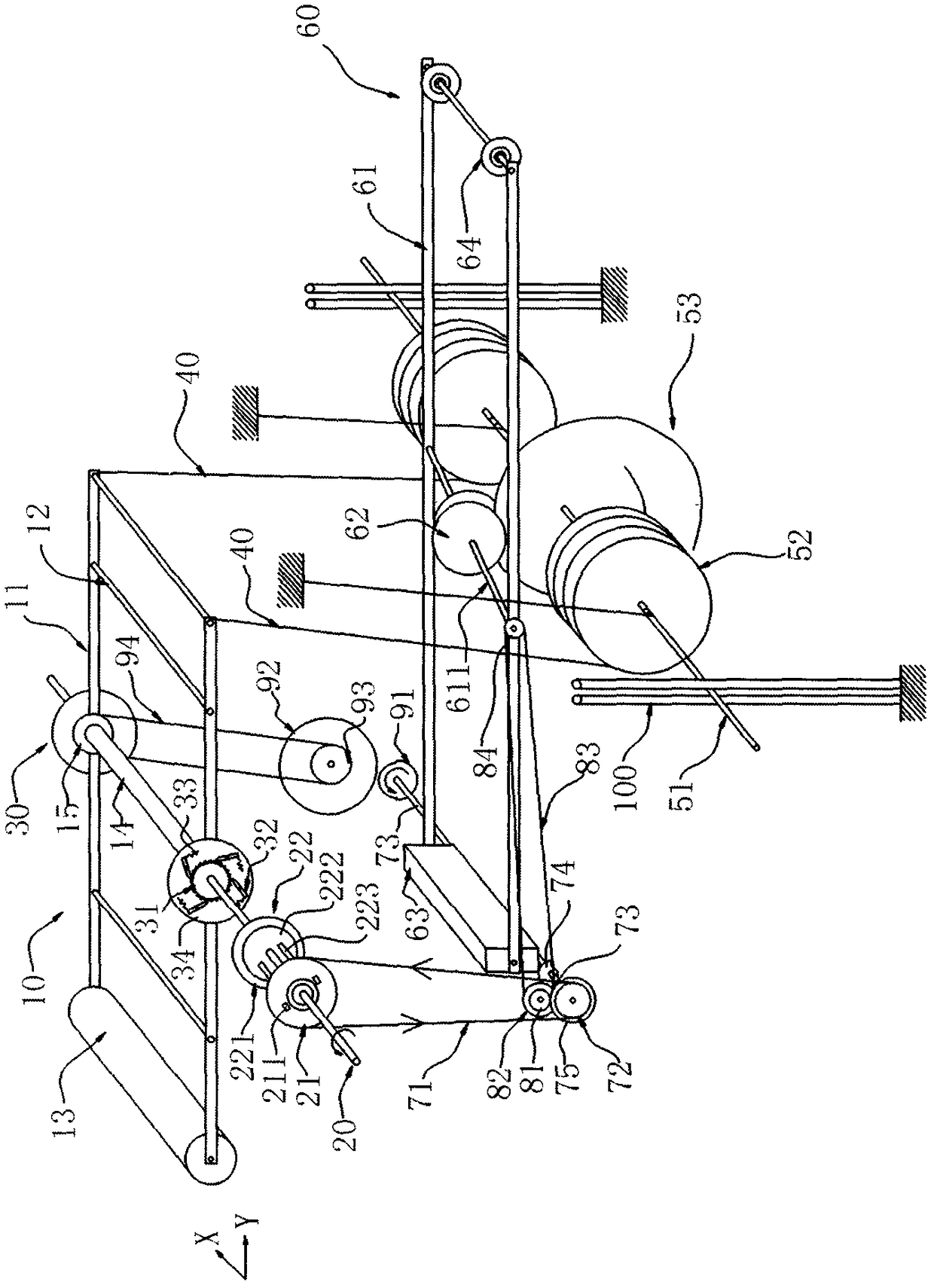
[0042] See figure 1 , Which is a schematic diagram of the overall structure of a power output device of the present invention, which includes a frame (not shown) and at least two drive units along the length direction of the frame (ie, the X-direction) arrangement. It is worth mentioning that the number of drive units can also be set to be greater than two, and multiple drive units are arranged in sequence along the length of the rack.

[0043] The drive unit is the power component of the entire device. The structure of the two drive units and the size of the ...


PUM


Abstract

The invention discloses a power take-off device comprising at least two driving units. Each driving unit comprises a main shaft, a swing frame, pull ropes, a suspension component, a pressure component, a synchronizing mechanism, a transmission mechanism and a limiting mechanism; and the main shafts of the two driving units are arranged in sequence and connected synchronously in the length direction of a rack. According to the power take-off device, the gravity of a first counter weight block is applied to the swing frame, and transmitted to the main shafts through a ratchet mechanism, so thata force source is provided for rotation of the main shafts; the gravity of a second counter weight block is applied to the suspension component, and the force source is transmitted to the other end ofthe swing frame through the pull ropes, so that the driving units are restored to the initial state to do work for rotation of the main shafts repeatedly, so that the main shafts can be continuouslyrotated under the condition that additional power is not provided or the additional power is lower; thus, the rotation power is output. Therefore, according to the power take-off device, the consumption of coal, gasoline, natural gas and other energy sources can be reduced, and no harmful substance is discharged to atmospheric environment; and the environmental pollution is reduced.

Description

Technical field [0001] The invention relates to the technical field of machinery, in particular to a power output device. Background technique [0002] With the gradual deterioration of the natural environment and the increasing shortage of energy, people’s requirements for energy-saving and environmentally friendly mechanical power output devices are gradually increasing. Current generators usually use coal as the energy source, and the coal is burned to drive the generator set. The generator sets generate electricity under high-speed rotation, thereby converting coal into electricity. However, this approach has relatively low energy utilization, and during the combustion process of coal, a large amount of harmful substances are emitted into the atmosphere, which is harmful to the environment. The pollution is greater. In addition, some use solar power generation. Although solar power generation can solve the problem of environmental pollution and is a sustainable renewable ene...

Claims


Application Information

Patent Timeline
Patent Type & Authority Applications(China)
IPC IPC(8): F03G3/06
CPCF03G3/06
Inventor 凌宏一凌远峰
Owner 凌宏一
Why Eureka
Try Eureka