Dual-layer hot air distribution pipe

A hot air distribution, double-layer technology, applied in the direction of pipes, branch pipelines, pipes/pipe joints/pipe fittings, etc., can solve the problems of low temperature on both sides, uneven temperature distribution, obvious thermal deformation, etc., and achieve the goal of improving the quality of hot air difference, solve the effect of uneven temperature distribution and uniform temperature distribution

Active Publication Date: 2018-12-07
SHANDONG UNIV OF TECH
View PDF7 Cites 0 Cited by
  • Summary
  • Abstract
  • Description
  • Claims
  • Application Information

AI Technical Summary

Problems solved by technology

This heating start technology has the advantages of simple structure, easy control, etc., but there are also many disadvantages: for example, after the electric heater stops heating, it is easy to oxidize and become brittle in the high temperature zone of the oxidizing atmosphere for a long time, or even break, and lose the function of restarting.
But there are problems: (1) The temperature distribution on the same cross-section of the oxidation bed is not uniform, the central temperature is high, the temperature on both sides is low, the front side temperature is high, and the rear side temperature is low, which affects the establishment of the entire temperature field of the oxidation bed and the maintenance of the device. The oxidation rate will have a great impact; for the drying space of the drying device, there is also the problem of uneven temperature distribution. The bigger the space, the worse the drying effect
(2) For a larger heating space, due to the longer heat distribution pipeline, the overall thermal deformation is more obvious
[0007] The reason is that in the process of hot air distribution, along with the outward heat dissipation of the pipe wall, whether along the main pipe or along the branch pipes, the temperature of the hot air gradually decreases from front to back. The key factor of temperature unevenness, and the effect of simple structural adjustment is not obvious, and the essential problem cannot be solved

Method used


Image

  • Dual-layer hot air distribution pipe
  • Dual-layer hot air distribution pipe
  • Dual-layer hot air distribution pipe

Examples


Embodiment 1

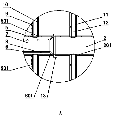
[0046] Such as Figure 1~5 As shown: in this embodiment, the main pipe 1 is provided with three sections connected head to tail along the axial direction, and the left end of each section of the main pipe 1 is the air inlet end, and the right end is the air outlet end. 2. Three branch pipes 3 are evenly distributed on the upper and lower sides of each section of the main pipe 1. The branch pipes 3 are arranged along the radial direction of the main pipe 1. The right end of the main pipe end pipe 2 is closed, and the upper and lower sides of the main pipe end pipe 2 are also symmetrically arranged. Three branch pipes 3. The end of each branch pipe 3 close to the main pipe 1 or the end pipe 2 of the main pipe is the air inlet end, and the end of each branch pipe 3 far away from the main pipe 1 or away from the main pipe end pipe 2 is the gas outlet end, and each branch pipe 3 is provided with a head-to-tail connection in the axial direction In the two sections, the gas outlet e...

Embodiment 2

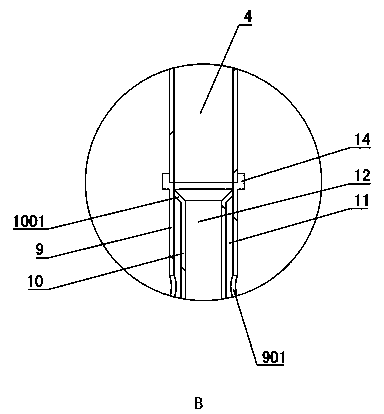
[0058] Such as Figure 6~7 As shown: the difference between embodiment 2 and embodiment 1 is that the delivery main pipe docking cover 601 of the main delivery main pipe 6 is spaced apart from the inner wall of the corresponding distribution main pipe 5 of this section, that is, both ends of the main pipe distribution chamber 8 are open. The delivery branch pipe docking cover 1001 of the delivery branch pipe 10 is spaced apart from the inner wall of the corresponding distribution branch pipe 9 , that is, both ends of the distribution chamber 11 of the branch pipe are open. Ensure that the hot air flow is more stable.

Embodiment 3

[0060] Such as Figure 8~12 As shown: the difference between embodiment 3 and embodiment 1 is that a pre-allocation main pipe 16 is arranged between the distribution main pipe 5 and the conveying main pipe 6 of each section of main pipe 1, and the pre-allocation main pipe 16 is connected with the corresponding distribution main pipe 5 and the conveying main pipe 6 They are evenly spaced so that a main pipe distribution cavity 8 is formed between the pre-distribution main pipe 16 and the distribution main pipe 5, and a main pipe pre-distribution chamber 18 is formed between the delivery main pipe 6 and the pre-distribution main pipe 16. The intake end of the conveying main pipe 6 is arranged within the intake end of the pre-distribution main pipe 16, so that the air inlet for connecting the pre-distribution main pipe 16 intake end and the conveying main pipe 6 intake end is formed at the pre-distribution main pipe 16 intake end. The main pipe communicates with the chamber 17. ...


PUM


Abstract

The invention discloses a dual-layer hot air distribution pipe, and belongs to the technical field of ultra-low concentration methane heat counter-current oxidation and low-density energy recycling. The pipe is characterized by comprising main pipes (1) and multiple branches (3) arranged on the two sides of the main pipes (1); and the air outlet end of each main pipe (1) is provided with a main pipe end pipe (2), each main pipe (1) comprises a conveying main pipe (6) and a distribution main pipe (5) which are sequentially arranged from inside to outside, the air outlet end of each conveying main pipe (6) communicates with the conveying main pipe (6) and a main pipe distribution cavity (8) of the next segment of the main pipe (1) at the same time, each branch pipe (3) comprises a conveyingbranch pipe (10) and a distribution branch pipe (9) which are sequentially arranged from inside to outside, and the air outlet end of each conveying branch pipe (10) communicates with the conveying branch pipe (10) and the distribution branch pipe (9) of the next segment of branch pipe (3) at the same time. The dual-layer hot air distribution pie solves the problem that temperature distribution isnot uniform thoroughly, and temperature distribution of an oxide bed on the same cross section is more uniform.

Description

technical field [0001] A double-layer hot air distribution pipe belongs to the technical field of ultra-low concentration methane thermal countercurrent oxidation and low-density energy recovery. Background technique [0002] The main component of coal mine gas is methane, which is both a gas energy source and a greenhouse gas. In addition to partial extraction, most of the gas is directly discharged into the atmosphere through the coal mine ventilation system, causing energy waste and air pollution. Thermal flow-reversal reactor (TFRR for short) in coal mine exhaust air can oxidize methane in exhaust air into carbon dioxide and water, realizing the utilization of low-quality energy and reducing greenhouse gas emissions. [0003] Before the coal mine exhaust air gas oxidation device is in normal operation, it needs to use a certain amount of energy to heat the central part of the oxidation bed to about 900~1000°C, and form a certain temperature distribution, which will dire...

Claims


Application Information

Patent Timeline
Patent Type & Authority Applications(China)
IPC IPC(8): F16L41/02
CPCF16L41/021
Inventor 尤彦彦刘永启高振强刘瑞祥毛明明
Owner SHANDONG UNIV OF TECH
Why Eureka
Try Eureka