Solar cell preparation method and solar cell module

A solar cell and module technology, applied in electrical components, circuits, photovoltaic power generation, etc., can solve the problem of low output power of solar cell modules, and achieve the effect of reducing current, reducing electrical loss, and preventing fragmentation

Active Publication Date: 2018-12-07
YINGLI ENERGY CHINA
View PDF9 Cites 2 Cited by
  • Summary
  • Abstract
  • Description
  • Claims
  • Application Information

AI Technical Summary

Problems solved by technology

[0003] In view of this, the embodiments of the present invention provide a method for preparing a solar cell and a solar cell module, so as to solve the problem of low output power of the solar cell module in the prior art

Method used


Image

  • Solar cell preparation method and solar cell module
  • Solar cell preparation method and solar cell module
  • Solar cell preparation method and solar cell module

Examples


Embodiment 1

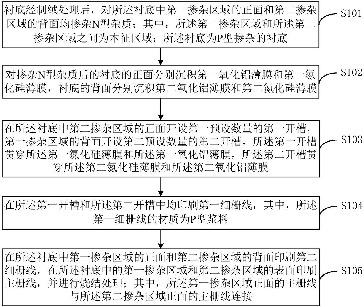
[0035] Please refer to figure 1 , the preparation method of solar cell comprises:

[0036] Step S101, after the substrate is textured, both the front side of the first doped region and the back side of the second doped region in the substrate are doped with N-type impurities; wherein, the first doped region and the Intrinsic regions are between the second doped regions; the substrate is a P-type doped substrate.

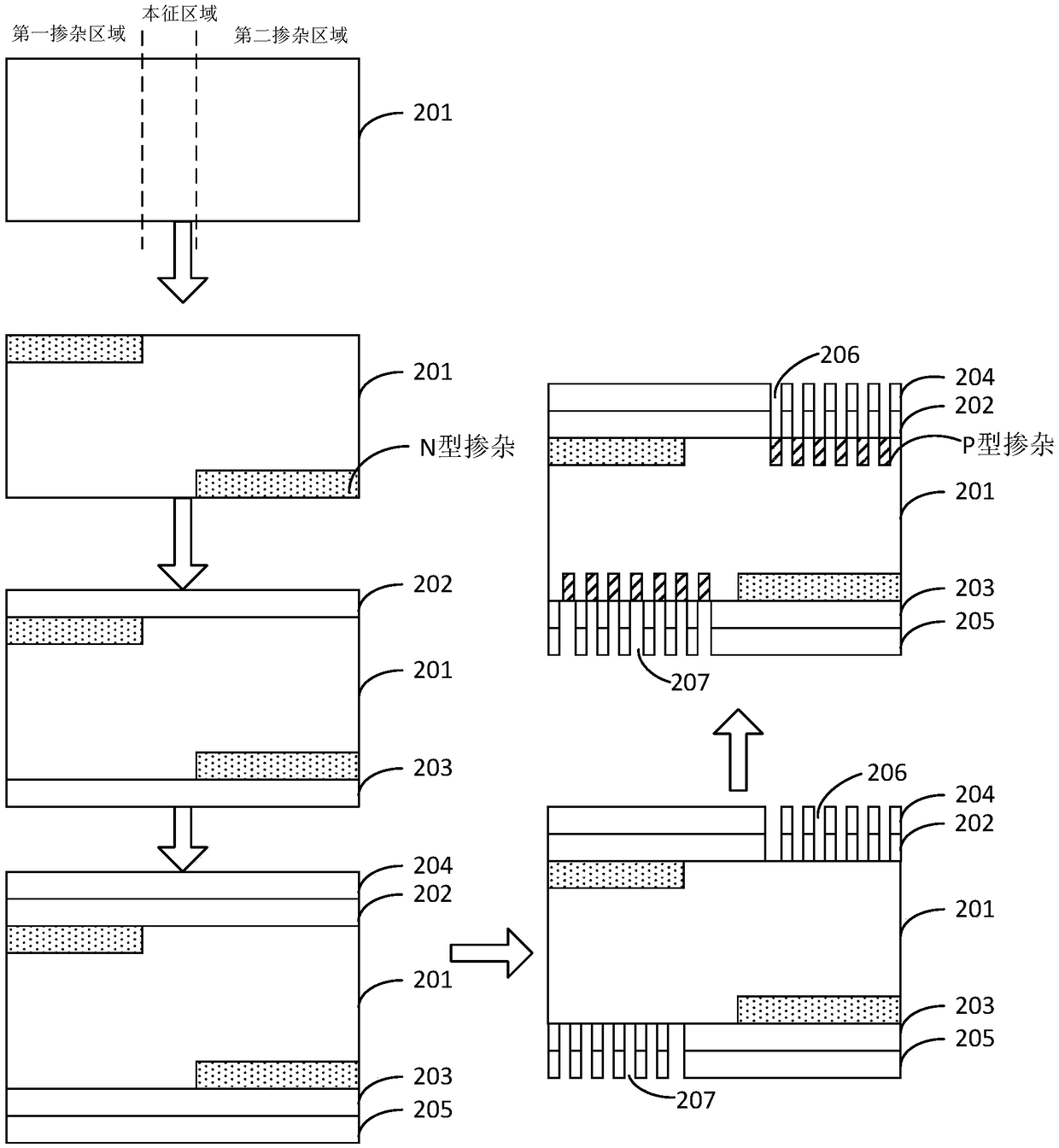
[0037] In the embodiment of the present invention, the substrate 201 is a P-type silicon substrate, and a passivated emitter and a rear local contact (Passivated Emitter Rear Contact, PERC) cell are prepared on the P-type silicon substrate. Such as figure 2 As shown, the substrate 201 is divided into a first doped region, an intrinsic region and a second doped region. The shapes of the first doped region, the second doped region and the intrinsic region include but are not limited to rectangles, trapezoids, triangles and other polygons. Preferably, the first dop...

Embodiment 2

[0065] A solar cell, which is prepared by the method for preparing a solar cell as described in Embodiment 1 of the present invention, and has the beneficial effects of Embodiment 1 of the present invention.

Embodiment 3

[0067] Please refer to Figure 5 and Figure 6 , a solar cell assembly obtained by connecting a plurality of solar cells as described in Embodiment 2 of the present invention through a ribbon 300, and has the beneficial effects of Embodiment 2 of the present invention.

[0068] Optionally, the soldering ribbon 300 is disposed on the backlight surface of the plurality of solar cells.

[0069] In the embodiment of the present invention, no welding ribbon is provided on the light-receiving surface of the solar cell, and the welding ribbon is arranged on the backlight surface of the solar cell, and two adjacent solar cells are connected in series through the welding ribbon 300, thereby reducing the usage of the welding ribbon 300 and reducing the Power loss due to ribbon shadowing.

[0070] Optionally, the width of the welding ribbon 300 is 1 mm to 3 mm.

[0071] In the embodiment of the present invention, the width of the welding ribbon 300 is controlled. When the width of the...


PUM

PropertyMeasurementUnit
widthaaaaaaaaaa
widthaaaaaaaaaa
thicknessaaaaaaaaaa

Abstract

The invention is applicable to the technical field of photovoltaic power generation, and provides a solar cell preparation method and a solar cell module. The method comprises: doping a front surfaceof a first doping area and a back surface of a second doping area in a substrate with N-type impurities after the substrate is subjected to a texturing process; depositing a first aluminum oxide filmand a first silicon nitride film on a front surface of the substrate, and depositing a second aluminum oxide film and a second silicon nitride film on a back surface of the substrate; forming first open slots in a front surface of the second doping area in the substrate, and forming second open slots on a back surface of the first doping area; preparing gate lines and performing a sintering process, wherein main gate lines on the front surface of the first doping area are connected to main gate lines on the front surface of the second doping region. The solar cell preparation method can prevent fragmentation of a solar cell caused by laser scribing, and can increase the output power of the solar cell module.

Description

technical field [0001] The invention belongs to the technical field of photovoltaic power generation, and in particular relates to a method for preparing a solar cell and a solar cell module. Background technique [0002] Photovoltaic power generation is an important field of new energy development, and improving the output power per unit area of ​​solar cells is the ultimate goal of photovoltaic technology progress. Existing solar cell modules usually cut the solar cells into multiple small cells by laser scribing, and then connect the small cells in series to form battery strings through welding ribbons. However, the electrical performance loss is caused by the welding ribbons, and , The laser scribing process will bring additional damage to the solar cell, resulting in a reduction in the output power of the solar cell module. Contents of the invention [0003] In view of this, the embodiments of the present invention provide a method for preparing a solar cell and a so...

Claims


Application Information

Patent Timeline
Patent Type & Authority Applications(China)
IPC IPC(8): H01L31/0224H01L31/0352H01L31/05H01L31/18
CPCH01L31/022433H01L31/0352H01L31/0504H01L31/18Y02E10/50Y02P70/50
Inventor 郎芳王子谦张伟张建旗孟庆超沈艳娇翟金叶张磊张向前李锋史金超
Owner YINGLI ENERGY CHINA
Why Eureka
Try Eureka