Multi-weighted opportunity beamforming system and method based on joint optimal power allocation

An optimal power and beamforming technology, applied in diversity/multi-antenna systems, transmission systems, radio transmission systems, etc., can solve the problems of low system transmission efficiency, achieve high transmission efficiency, simple algorithm, and convenient design

Active Publication Date: 2018-12-07
HARBIN INST OF TECH
View PDF5 Cites 6 Cited by
  • Summary
  • Abstract
  • Description
  • Claims
  • Application Information

AI Technical Summary

Problems solved by technology

[0004] The present invention provides a multi-weight opportunistic beamforming system based on joint optimal power allocation to solve the problem that the transmitting end of t

Method used


Image

  • Multi-weighted opportunity beamforming system and method based on joint optimal power allocation
  • Multi-weighted opportunity beamforming system and method based on joint optimal power allocation
  • Multi-weighted opportunity beamforming system and method based on joint optimal power allocation

Examples


specific Embodiment approach 1

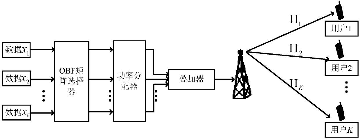
[0023] Specific implementation mode one: combine figure 1 This embodiment is described. The multi-weight opportunistic beamforming system based on joint optimal power allocation given in this embodiment specifically includes:

[0024] Transmitter and user end;

[0025] The transmitting end includes an OBF matrix selector, a power divider, a superposer and a radiation antenna array; OBF is opportunistic beamforming;

[0026] The OBF matrix selector is used to receive user data that needs to be sent, determine the input value of the OBF matrix, select the OBF matrix with the largest signal-to-noise ratio for each user data, and transmit the user data to the power divider;

[0027] The power allocator is used to perform joint optimal power allocation on all user data in one transmission, and transmit it to the superimposer;

[0028] The superimposer is used to superimpose and transmit the power-allocated user data to the radiating antenna array;

[0029] The radiating antenna ...

specific Embodiment approach 2

[0032] Specific implementation mode 2: The multi-weight opportunistic beamforming method based on joint optimal power allocation given in this implementation mode specifically includes the following steps:

[0033] Step 1. The OBF matrix selector at the transmitting end uses the joint optimal power allocation algorithm to determine the input value of the OBF matrix for this transmission (select the number of OBF matrices generated by the corresponding transmitting end when the system and rate are maximum in one transmission as the OBF matrix input value), and select the OBF matrix with the largest signal-to-noise ratio SNR for each user; OBF is opportunistic beamforming; the power allocator determines the power allocated to each user according to the input value of the OBF matrix, and performs power allocation on the corresponding user data send to stacker;

[0034] By optimally allocating the power of each user at the transmitting end of the system, the opportunistic beamform...

specific Embodiment approach 3

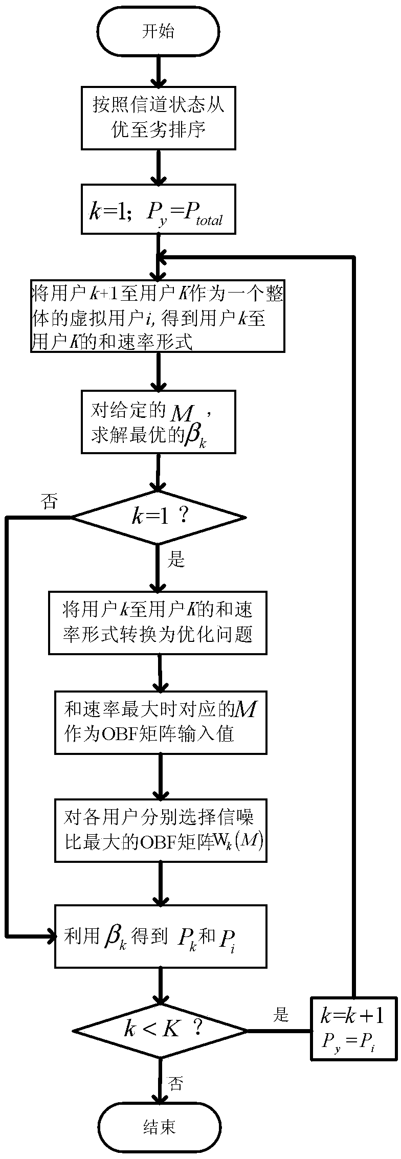
[0037] Specific implementation mode three: combination figure 2 This embodiment will be described. The difference between this embodiment and the second embodiment is that the first step specifically includes the following steps:

[0038] Step 11. The sending end sorts the K users according to the channel status from good to bad; K is the total number of users for this transmission; let k=1, P y =P total ;P y Indicates the sum of power allocated to user k to user K, P total Indicates the total power of the transmitter;

[0039] Step 12, user k+1 to user K is taken as a whole virtual user i, then the sum rate form of user k to user K is:

[0040]

[0041] Among them, R ∑ is the sum rate from user k to user K, and the sum rate from user 1 to user K is the sum rate of the system, T s is the total time to complete a transmission, τ is the pilot time of a transmission, W k (M) is the OBF matrix selected by user k, Wi(M) is the OBF matrix selected by virtual user i; N 0 ...


PUM


Abstract

The invention provides a multi-weighted opportunity beamforming system and method based on joint optimal power allocation and belongs to the technical field of wireless communications. The system of the present invention comprises a transmitting end and a user end; the transmitting end comprises an OBF matrix selector, a power splitter, a superimposer and a radiating antenna array. The method of the present invention comprises the following steps: firstly, an OBF matrix selector determines an OBF matrix input value transmitted this time by using a joint optimal power allocation algorithm and an OBF matrix with the maximum signal-to-noise ratio is selected for each user; the power splitter determines the power allocated to each user; then, the superimposer performs superposition on the userdata subjected to power allocation and the user data is transmitted to the radiating antenna array; the radiating antenna array performs broadcast; finally, each user end obtains the broadcast data and carries out decoding, respectively. The multi-weighted opportunity beamforming system and method based on joint optimal power allocation in the invention solve the problem that the transmitting endof the prior art can only serve one user at one transmission moment, resulting in low transmission efficiency of the system. The multi-weighted opportunity beamforming system and method based on joint optimal power allocation in the invention can be used for opportunistic beamforming.

Description

technical field [0001] The invention relates to a multi-weight opportunistic beamforming system and method, and belongs to the technical field of wireless communication. Background technique [0002] The fifth-generation mobile communication technology (5th-Generation, 5G) aims to provide higher-speed and more reliable communication services. In the current situation of limited wireless resources, in order to achieve higher communication performance, it is necessary to adopt higher spectrum utilization. communication technology. MIMO beamforming technology uses the space domain to greatly improve the bit error rate and system capacity performance of wireless communication systems. Therefore, beamforming technology has become the core technology of future communication technologies. However, the transmitter needs complete channel state information. Shaping technology can introduce the most important assumptions of diversity and multiplexing gain. This assumption is often rea...

Claims


Application Information

Patent Timeline
IPC IPC(8): H04B7/0426H04B7/06
CPCH04B7/043H04B7/0617Y02D30/70
Inventor 于启月孙文彬郭继冲孟维晓
Owner HARBIN INST OF TECH
Why Eureka
Try Eureka