Automatic machining clamp with multi-directional adjustment function

A multi-directional adjustment and fixture technology, used in manufacturing tools, metal processing equipment, metal processing mechanical parts, etc., can solve the problems of low production efficiency, trouble, time-consuming and laborious, and achieve fast clamping speed, convenient use, and easy processing. The effect of positioning

Inactive Publication Date: 2018-12-11
DONGGUAN KAILEDI NUMERICAL CONTROL SCI & TECH CO LTD
View PDF3 Cites 14 Cited by
  • Summary
  • Abstract
  • Description
  • Claims
  • Application Information

AI Technical Summary

Problems solved by technology

[0004] The existing fixtures are manually clamped, which is very troublesome; the position of the fixtures needs to be manually adjusted many times for proofreading before processing, which is time-consuming and laborious, and the production efficiency is low

Method used


Image

  • Automatic machining clamp with multi-directional adjustment function
  • Automatic machining clamp with multi-directional adjustment function
  • Automatic machining clamp with multi-directional adjustment function

Examples


Embodiment 1

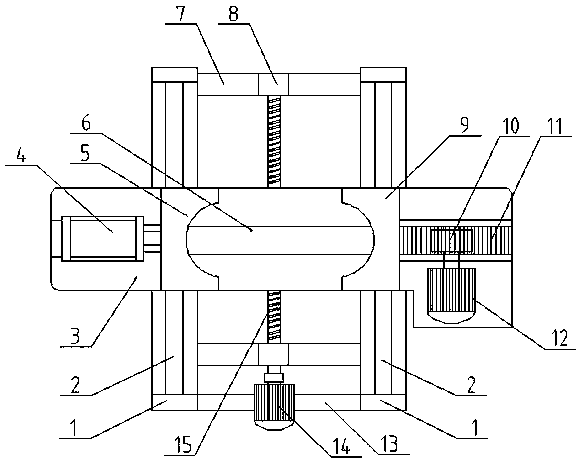
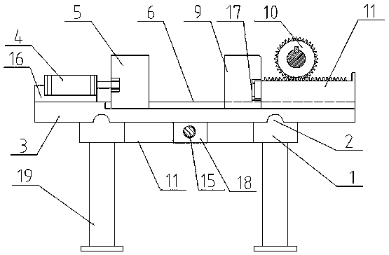
[0032] see Figure 1-3 , this embodiment provides a multi-directional adjustable automatic processing fixture, including a first bracket 1, a second bracket 3, a cylinder 4, a first clamping block 5, a second clamping block 9, a first motor 12, a second motor 14. Screw rod 15, leg 19; the lower part of the first bracket 1 is provided with a leg 19, the middle of the first bracket 1 is provided with a second motor 14, and the second motor 14 is fixedly connected to the screw rod 15; the second bracket 3 Set on the top of the first bracket 1, the first clamping block 5 and the second clamping block 9 are installed on the second bracket 3, the left side of the second bracket 3 is provided with a cylinder 4, and the cylinder 4 is installed on the cylinder support 16, and the cylinder The support 16 is fixedly connected to the second bracket 3, the cylinder 4 is fixedly connected to the first clamping block 5, and the first motor 12 is arranged on the right side of the second brack...

Embodiment 2

[0037] see see Figure 4 , the structure of this implementation is the same as that of Embodiment 1, the first clamping block 5 is replaced by the third clamping block 21, the second clamping block 9 is replaced by the fourth clamping block 22, the third clamping block 21 and the fourth clamping block 22 Compatible with cylindrical workpieces that can be clamped horizontally.

[0038] Working principle of the present invention:

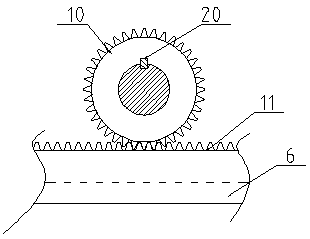
[0039] This embodiment provides a multi-directional adjustable automatic processing fixture, the first clamping block 5 and the second clamping block 9 are installed on the second guide rail 6, the cylinder 4 pushes the first clamping block 5 to the right, The rotation of the first motor 12 drives the gear 10 to rotate, the rack 11 pushes the second clamping block 9 to move to the left, the first clamping block 5 cooperates with the second clamping block 9 to clamp the workpiece, and the pressure sensor 17 senses that the clamping force reaches the s...


PUM


Abstract

The invention provides an automatic machining clamp with a multi-directional adjustment function, and belongs to the field of machining equipment. The automatic machining clamp comprises a first bracket, a second bracket, an air cylinder, a first clamping block, a second clamping block, a first motor, a second motor, a lead screw and supporting legs; and the supporting legs are arranged on the lower portion of the first bracket, the second motor is arranged in the middle of the first bracket, the second motor is fixedly connected with the lead screw, the second bracket is arranged on the upperportion of the first bracket, the first clamping block and the second clamping block are mounted on the second bracket, the air cylinder is arranged on the left side of the second bracket, the air cylinder is fixedly connected with the first clamping block, and the first motor is arranged on the right side of the second bracket. The automatic machining clamp is simple in structure, stable in operation and easy to maintain; workpieces are automatically clamped, the clamping speed is high, and the efficiency of workpiece mounting is high; the workpiece mounting position can be adjusted in the multiple directions, machining and positioning are facilitated, and the production efficiency is improved; and the multiple clamping blocks are arranged, and thus the automatic machining clamp is applied to clamping of the workpieces with different shapes, and is high in applicability and convenient to use.

Description

technical field [0001] The invention relates to a mechanical processing equipment, in particular to a multi-directional adjustable automatic processing fixture. Background technique [0002] The fixture is a clamping device used to quickly, conveniently and safely install the workpiece during the machining process. For example, it is often necessary to maintain the correct positional relationship during stamping, riveting, welding, pasting or solidification of the workpiece. Commonly used fixtures include Welding fixtures, inspection fixtures, assembly fixtures, machine tool fixtures, etc., among which machine tool fixtures are the most common. [0003] When processing a workpiece on a machine tool, in order to make the surface of the workpiece meet the technical requirements such as the size, geometric shape, and mutual position accuracy with other surfaces specified in the drawing, the workpiece must be installed and clamped firmly before processing. Fixtures with differen...

Claims


Application Information

Patent Timeline
Patent Type & Authority Applications(China)
IPC IPC(8): B23Q3/08B23Q17/00
CPCB23Q3/08B23Q17/005B23Q2703/04
Inventor 郭良山
Owner DONGGUAN KAILEDI NUMERICAL CONTROL SCI & TECH CO LTD
Why Eureka
Try Eureka