
An intelligent slag removing method of molten iron based on machine vision

A machine vision, slag removal technology, applied in the field of image recognition, metallurgy and image processing, can solve the problems of the sulfur content of molten steel exceeding the standard, affecting the quality of steelmaking, and not being able to achieve it, so as to reduce the sulfur content and improve the slag removal. Efficiency and accuracy, the effect of small amount of calculation

Inactive Publication Date: 2018-12-11
CISDI INFORMATION TECH CO LTD +1
View PDF7 Cites 15 Cited by
  • Summary
  • Abstract
  • Description
  • Claims
  • Application Information

AI Technical Summary

Problems solved by technology

[0003] The sulfur content of molten steel is a key parameter in the steelmaking process. If the slag removal is not in place before the molten iron is injected into the converter, the sulfur content of the molten steel will exceed the standard, thereby affecting the quality of steelmaking.
At present, the slag removal of molten iron in the industry is still based on the traditional method of manual control of slag removal and shovel removal. This method cannot achieve the most effective slag removal effect, and the environment of this station is harsh
[0004] However, there is currently no effective method for intelligent slag removal in ladles, and a new technical means is urgently needed, which can identify the position of desulfurization slag on the surface of the ladle and the most concentrated position of desulfurization slag, and control the removal of slag. The slag shovel removes slag in this area to ensure the reliability of the automatic molten iron slag removal equipment

Method used


Image

  • An intelligent slag removing method of molten iron based on machine vision
  • An intelligent slag removing method of molten iron based on machine vision
  • An intelligent slag removing method of molten iron based on machine vision

Examples


Embodiment Construction

[0026] Embodiments of the present invention are described below through specific examples, and those skilled in the art can easily understand other advantages and effects of the present invention from the content disclosed in this specification. The present invention can also be implemented or applied through other different specific implementation modes, and various modifications or changes can be made to the details in this specification based on different viewpoints and applications without departing from the spirit of the present invention. It should be noted that, in the case of no conflict, the following embodiments and features in the embodiments can be combined with each other.

[0027] It should be noted that the diagrams provided in the following embodiments are only schematically illustrating the basic ideas of the present invention, and only the components related to the present invention are shown in the diagrams rather than the number, shape and shape of the compo...


PUM


Abstract

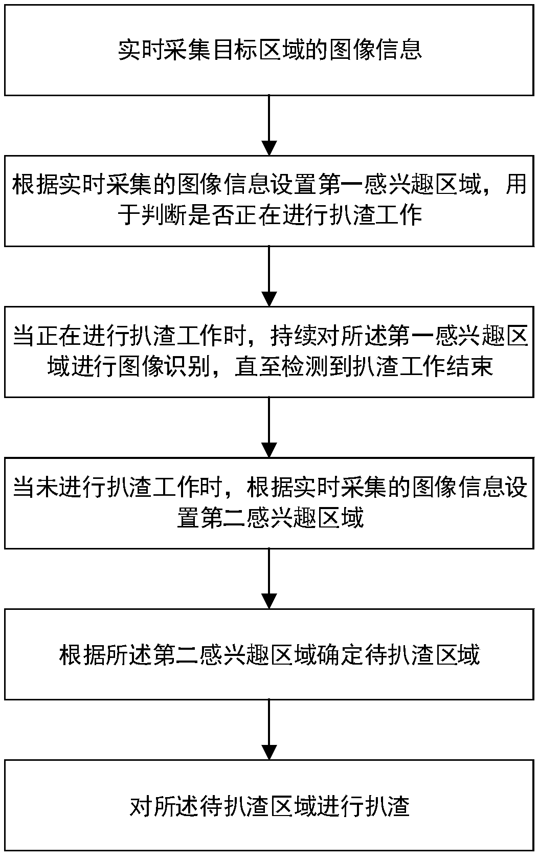
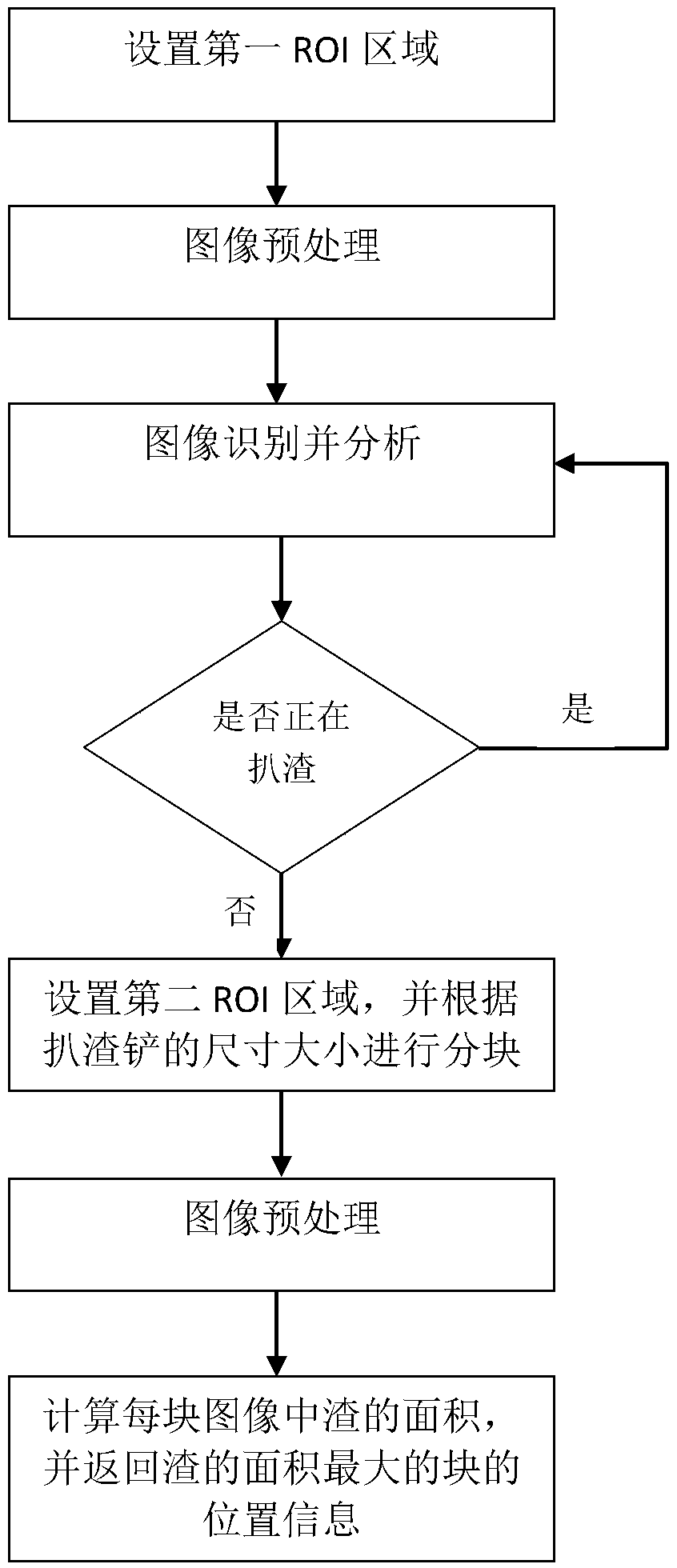
The invention provides an intelligent slag removing method of molten iron based on machine vision, which comprises the following steps: collecting image information of a target area in real time; setting a first region of interest according to the image information collected in real time for judging whether the slag scraping work is being carried out; when the slag scavenging work is in progress,continuously performing image recognition on the first region of interest until the end of the slag scavenging work is detected; setting a second region of interest according to the image informationcollected in real time when the slag scraping is not carried out; determining a region to be stripped according to the second region of interest; carrying out slag scraping on the area to be scraped.According to the invention, the area with the most slag content on the surface of molten iron can be effectively and accurately measured and the signal is returned to the automation equipment for subsequent slag scraping, and the efficiency and accuracy of slag scraping can be significantly improved. The method has the advantages of easy realization, small calculation amount and strong stability,and can also meet the requirements of real-time processing and ensure the accuracy of slag scraping.

Description

technical field [0001] The invention relates to the fields of metallurgy, image processing, and image recognition, and in particular to an intelligent slag removal method for molten iron based on machine vision. Background technique [0002] In the steelmaking process, the molten iron after desulfurization treatment can be blended into the converter for steelmaking. However, only desulfurization treatment cannot completely remove the sulfur content in molten iron, because there is a large amount of desulfurization slag on the surface of molten iron after desulfurization treatment. If the slag is not removed in time, the sulfur element in the slag will be reduced by oxygen. The lower the requirement for the sulfur content of molten steel, the higher the removal rate of slag removal, and the lower the amount of slag in molten iron. [0003] The sulfur content of molten steel is a key parameter in the steelmaking process. If the slag removal is not in place before the molten i...

Claims


Application Information

Patent Timeline
Patent Type & Authority Applications(China)
IPC IPC(8): G06T7/00
CPCG06T7/0004G06T2207/30116G06T2207/30136
Inventor 庞殊杨刘向东贾鸿盛毛尚伟
Owner CISDI INFORMATION TECH CO LTD
Learn More