
Heating devices in proton exchange membrane fuel cell stacks

A fuel cell stack and proton exchange membrane technology, which is applied in the fields of fuel cell heat exchange, fuel cell, fuel cell additives, etc., can solve the problems of slow start of proton exchange membrane fuel cell, influence of fuel cell startup, and startup failure, etc. To achieve the effect of good heating effect, compact and ingenious structure, and short cold start time

Pending Publication Date: 2018-12-11
ZHANGJIAGANG RES INST OF HYDROGEN ENERGY CO LTD
View PDF12 Cites 2 Cited by
  • Summary
  • Abstract
  • Description
  • Claims
  • Application Information

AI Technical Summary

Problems solved by technology

Because the water produced by the chemical reaction will remain inside the proton exchange membrane fuel cell stack, in the low-temperature environment below the freezing point, the liquid water inside the fuel cell will freeze, and the reaction heat generated when the fuel cell is started is not enough to dissolve the ice. As far as the start-up of the fuel cell is affected, the proton exchange membrane fuel cell may have problems such as slow start-up, difficult start-up or start-up failure in harsh low-temperature environments

Method used


Image

  • Heating devices in proton exchange membrane fuel cell stacks
  • Heating devices in proton exchange membrane fuel cell stacks
  • Heating devices in proton exchange membrane fuel cell stacks

Examples


Embodiment 1

[0032] Environmental conditions: specific heat of graphite 710 J / (kg K); calorific value of hydrogen 1.4×10 8 J / kg; battery stack mass 200kg; ambient temperature -30°C; temperature after heating up 0°C; heat dissipation rate 5%.

[0033] Hydrogen consumption = (temperature after heating - ambient temperature) × specific heat of graphite × mass of battery stack ÷ calorific value of hydrogen × (1+ heat dissipation rate).

[0034] Hydrogen consumption=30×710×200÷(1.4×10 8 )×1.05=0.032kg.

Embodiment 2

[0036] Environmental conditions: ambient temperature -20°C; temperature after heating up 0°C; hydrogen consumption flow rate 0.048kg / min; graphite specific heat 710 J / (kg K); hydrogen calorific value 1.4×10 8 J / kg; battery stack mass 200kg; heat dissipation rate 5%.

[0037] Among them: the hydrogen consumption flow is determined according to the hydrogen supply capacity of the hydrogen supply system for the fuel cell system, and the working hydrogen consumption under the rated power of the fuel cell is determined, taking a 36kw fuel cell as an example.

[0038] Hydrogen consumption = (temperature after heating - ambient temperature) × specific heat of graphite × mass of battery stack ÷ calorific value of hydrogen × (1+ heat dissipation rate).

[0039] Hydrogen consumption=20×710×200÷(1.4×10 8 )×1.05=0.022kg.

[0040] Cold start time = hydrogen consumption ÷ hydrogen flow.

[0041] Cold start time=0.022÷0.048=0.46 min=28 s.

[0042] That is: from the ambient temperature -...

Embodiment 3

[0044] Environmental conditions: ambient temperature -10°C; temperature after heating up 0°C; hydrogen consumption flow rate 0.048kg / min; graphite specific heat 710 J / (kg K); hydrogen calorific value 1.4×10 8 J / kg; battery stack mass 200kg; heat dissipation rate 5%.

[0045] Among them: the hydrogen consumption flow is determined according to the hydrogen supply capacity of the hydrogen supply system for the fuel cell system, and the working hydrogen consumption under the rated power of the fuel cell is determined, taking a 36kw fuel cell as an example.

[0046] Hydrogen consumption = (temperature after heating - ambient temperature) × specific heat of graphite × mass of battery stack ÷ calorific value of hydrogen × (1+ heat dissipation rate).

[0047] Hydrogen consumption=10×710×200÷(1.4×10 8 )×1.05=0.011kg.

[0048] Cold start time = hydrogen consumption ÷ hydrogen flow.

[0049] Cold start time=0.011÷0.048=0.23 min=14 s.

[0050] That is: from the ambient temperature -...


PUM


Abstract

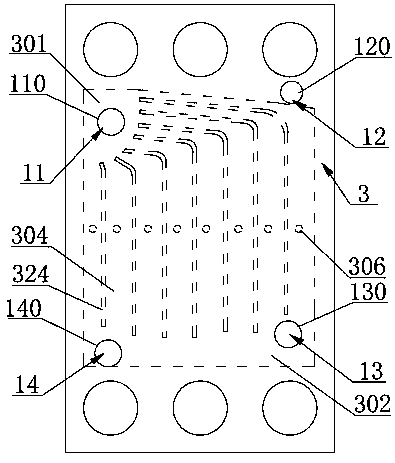
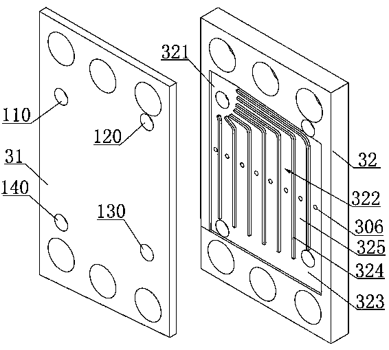
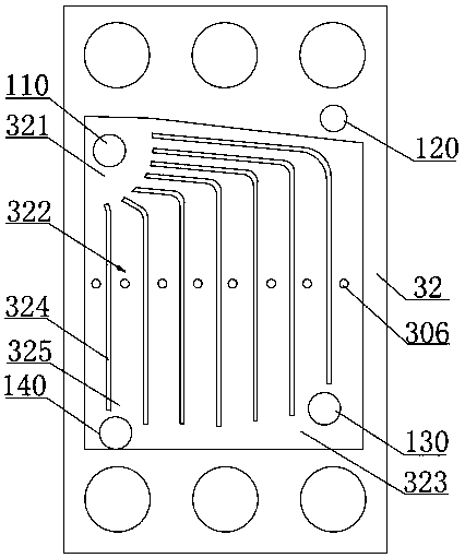
The invention discloses a heating device in a proton exchange membrane fuel cell stack. The device includes a heating body, An air collecting and distributing cavity, a collecting cavity, a hydrogen collection and distribution chamber, a plurality of air passages and a plurality of hydrogen passages are arranged in the heating body. An inlet end and an outlet end of the air flow passage are respectively communicated with an air collecting and distributing cavity and a collecting cavity, The inlet end of the hydrogen gas flow passage is communicated with the hydrogen gas collecting and distributing cavity, and a combustion port communicated with the corresponding hydrogen gas flow passage is arranged on the flow passage wall of each air flow passage, the hydrogen gas in each hydrogen gas flow passage can enter into the corresponding air flow passage through the combustion port, and an igniter is arranged at the combustion port of each air flow passage; The air collecting and distributing cavity is communicated with the heating air channel; The hydrogen gas collecting and distributing cavity is communicated with the heating hydrogen gas channel; The collecting chamber is communicatedwith the exhaust passage and the drain passage. The invention has the advantages that the heating effect is good, and the proton exchange membrane fuel cell can be reliably started under the ultra-low temperature condition.

Description

technical field [0001] The invention relates to the technical field of proton exchange membrane fuel cells, in particular to a stack of proton exchange membrane fuel cells. Background technique [0002] The structure of the proton exchange membrane fuel cell mainly includes: several single cells arranged between a pair of end plates. Proton exchange membrane fuel cell is an electrochemical power generation device that uses hydrogen and oxygen as raw materials to electrochemically react to generate water and convert chemical energy into electrical energy at the same time. It has the characteristics of cleanness, high efficiency, energy saving and environmental protection, and high energy conversion rate. Because the water produced by the chemical reaction will remain inside the proton exchange membrane fuel cell stack, in the low-temperature environment below the freezing point, the liquid water inside the fuel cell will freeze, and the reaction heat generated when the fuel c...

Claims


Application Information

Patent Timeline
Patent Type & Authority Applications(China)
IPC IPC(8): H01M8/04014
CPCH01M8/04022Y02E60/50
Inventor 严岩吕青青倪中华丁桓展郁永斌魏蔚唐健
Owner ZHANGJIAGANG RES INST OF HYDROGEN ENERGY CO LTD
Learn More