Liquid crystal-based electric control scanning waveguide leaky wave antenna

A technology of leaky wave antenna and scanning wave, which is applied in the field of leaky wave antenna based on liquid crystal electronically controlled scanning waveguide, which can solve the problems of deterioration of antenna radiation characteristics and complex antenna control mechanism, etc.

Inactive Publication Date: 2018-12-11
江苏万邦微电子有限公司
View PDF4 Cites 7 Cited by
  • Summary
  • Abstract
  • Description
  • Claims
  • Application Information

AI Technical Summary

Problems solved by technology

However, the existing liquid crystal electronically scanned leaky-wave antennas usually have the following disadvantages: first, it is necessary to use an external controllable magnetic field to match the pattern scanning of the antenna, which makes the control mechanism of the antenna complicated; second, in order to make the liquid crystal The dielectric constant of the antenna changes under the action of an external electric field, and an additional bias circuit needs to be designed for the antenna, and this bias circuit will cause electromagnetic coupling between the low-frequency or DC circuit and the radio-frequency circuit, thereby affecting the radiation characteristics of the antenna. deterioration

Method used


Image

  • Liquid crystal-based electric control scanning waveguide leaky wave antenna
  • Liquid crystal-based electric control scanning waveguide leaky wave antenna
  • Liquid crystal-based electric control scanning waveguide leaky wave antenna

Examples


Embodiment Construction

[0018] The present invention is described below in conjunction with accompanying drawing:

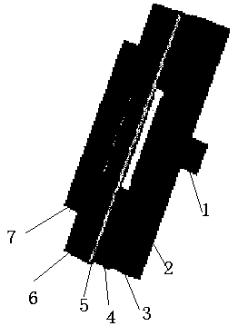
[0019] Such as figure 1 As shown, is a side structural view of one of the N unit arrays in the present invention. From bottom to top, the cell array includes microstrip line 1, dielectric substrate 2, insulating layer 3, lower metal floor 4, liquid crystal layer 5, upper metal floor 6, and metal patch 7; In the middle of the lower surface of the unit array; there is a gap in the middle of the upper metal floor, and the shape of the gap from the side is H-shaped; the gap between the two metal floors and the H-shaped gap is filled with liquid crystal material; the metal patch Make at least one rectangular slit in the middle.

[0020] The invention is a microstrip leaky-wave antenna designed based on printed circuit board technology. Considering that the liquid crystal material has excellent characteristics such as adjustable dielectric constant, low loss, and ability to work in a highe...


PUM


Abstract

The invention particularly relates to a liquid crystal-based electric control scanning waveguide leaky wave antenna, which comprises N unit arrays, wherein N is larger than or equal to 2; the N unit arrays are embedded into a dielectric substrate, and is characterized in that the unit array sequentially comprises a micro-strip line, a dielectric substrate, a lower-layer metal floor, a liquid crystal layer, an upper-layer metal floor and a metal patch from bottom to top. The micro-strip line is located in the middle of the lower surface of the unit arrays; a gap is formed in the middle of the upper-layer metal floor, and the gap is H-shaped when viewed from the side face. Liquid crystal material is filled between the two metal floors and the H-shaped gap; and at least one rectangular gap isformed in the middle of the metal patch. According to the antenna, no phase shifter can be realized, and the target radiation characteristic of the antenna can be realized only by using an amplitude-weighted beam control method to change the amplitude of an array element without changing the phase and the antenna parameters.

Description

technical field [0001] The invention belongs to the technical field of microwave antennas, and in particular relates to a liquid crystal electronically controlled scanning waveguide leaky wave antenna. Background technique [0002] Leaky-wave antennas have frequency scanning characteristics in which the beam direction of the main lobe of the antenna changes as the frequency of the fed electromagnetic wave changes. The frequency sweep characteristic of the leaky wave antenna has been widely used in the past, but this frequency sweep characteristic often occupies a relatively wide continuous frequency band resource. Nowadays, with the explosive development of wireless communication, the already limited spectrum resources are increasingly congested, and the frequency scanning characteristics of traditional leaky wave antennas are obviously contradictory to the pursuit of modern communication to improve spectrum utilization. Therefore, in order to solve this contradiction , the...

Claims


Application Information

Patent Timeline
Patent Type & Authority Applications(China)
IPC IPC(8): H01Q1/38H01Q3/28H01Q13/20
CPCH01Q1/38H01Q3/28H01Q13/206
Inventor 张春秋杨亮亮张燕
Owner 江苏万邦微电子有限公司
Why Eureka
Try Eureka