Optical fiber laser lamp pattern painting device

A technology of laser light and optical fiber, applied in the direction of spraying device, paint booth, etc., can solve problems such as accuracy improvement, pattern damage, poor pattern quality, etc., to achieve the effect of improved accuracy, convenient use, and avoidance of skew.

Inactive Publication Date: 2018-12-14
苏州高新区建金建智能科技有限公司
View PDF7 Cites 4 Cited by
  • Summary
  • Abstract
  • Description
  • Claims
  • Application Information

AI Technical Summary

Problems solved by technology

[0004] However, for the above-mentioned equipment, large-scale digital spraying equipment often has a higher price and high use cost, while small-scale manual spraying equipment has low spraying accuracy and poor quality of sprayed patterns, and small-scale manual spraying equipment often needs to be sprayed after spraying. Natural air drying will easily cause pattern damage. Small manual spraying equipment does not have the function of fiber laser light calibration. It is impossible to see the precise position of pattern spraying before spraying, which is not conducive to the improvement of accuracy. Therefore, it is necessary to design an intelligent , High-precision small-scale spraying equipment is of great significance. For this reason, the present invention provides a fiber laser light pattern spraying device

Method used


Image

  • Optical fiber laser lamp pattern painting device
  • Optical fiber laser lamp pattern painting device
  • Optical fiber laser lamp pattern painting device

Examples


Embodiment approach

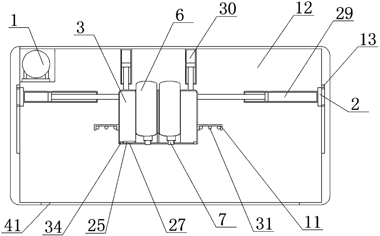
[0033] As a preferred embodiment of the present invention, the third electrode sheet 35 and the fourth electrode sheet 36 are electrically connected to the positive pole and the negative electrode of the electric valve 32 respectively, and the first electrode sheet 9 and the second electrode sheet 10 are connected to the electrode sheet three respectively. 35 contacts with electrode sheet four 36.

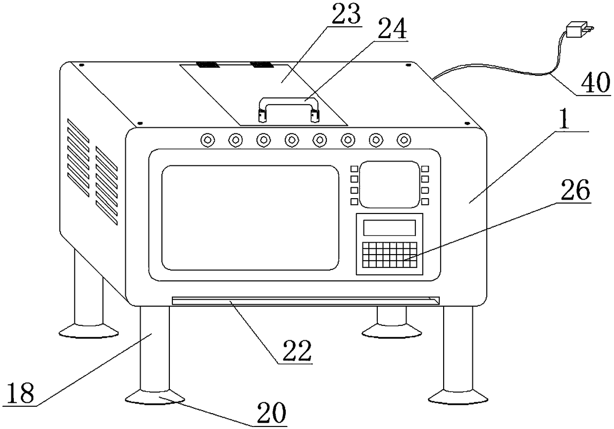
[0034] As a preferred embodiment of the present invention, the power cord 40 is respectively connected to the single chip microcomputer 25, the operation button 26, the distance sensor 27, the hydraulic rod one 28, the hydraulic rod two 29, the hydraulic rod three 30, the electric heating rod 31, Vacuum pump 33 and fiber laser lamp 34.

[0035] As a preferred embodiment of the present invention, a plug is connected to the power cord 40 , and a spraying port 41 is opened at the bottom of the housing 1 .

[0036] As a preferred embodiment of the present invention, the single-chip mi...


PUM


Abstract

The invention provides an optical fiber laser lamp pattern painting device. The optical fiber laser lamp pattern painting device comprises a shell, a painting mechanism and an intelligent processing system. The painting mechanism comprises a movable painting base and two movable plates. A sliding rod is fixedly arranged between the two movable plates. Sliding holes are formed in the movable painting base. The movable painting base sleeves the sliding rod through the sliding holes. A plurality of accommodating grooves are formed in the top of the movable painting base. Pressure paint cans are arranged in the accommodating grooves. Paint spray nozzles are arranged at the bottoms of the pressure paint cans. A plurality of convex through holes in one-to-one correspondence with the accommodating grooves are formed in the bottom of the movable painting base and communicate with the accommodating grooves. The inner side walls of the thicker ends of the convex through holes are provided with electrode plates I and electrode plates II. Drying seats are arranged on the two sides of the movable painting base respectively. The optical fiber laser lamp pattern painting device is reasonable in design, convenient to use, high in accuracy and capable of realizing high-efficiency painting.

Description

technical field [0001] The invention relates to a pattern painting device for an optical fiber laser lamp, which belongs to the technical field of optical fiber laser equipment. Background technique [0002] In industrial production and other production processes, it is often necessary to spray some patterns on the surface of the product to increase the aesthetics and recognition of the product, thereby improving the marketability index of the product. [0003] In the process of spraying patterns, it is necessary to use related spraying equipment, which are generally large-scale digital spraying equipment and small manual spraying equipment. [0004] However, for the above-mentioned equipment, large-scale digital spraying equipment often has a higher price and high use cost, while small-scale manual spraying equipment has low spraying accuracy and poor quality of sprayed patterns, and small-scale manual spraying equipment often needs to be sprayed after spraying. Natural ai...

Claims


Application Information

Patent Timeline
Patent Type & Authority Applications(China)
IPC IPC(8): B05B16/20B05B12/14B05B12/28B05B15/625B05B13/04
CPCB05B12/1472B05B12/28B05B13/041B05B15/625B05B16/20
Inventor 张秀平
Owner 苏州高新区建金建智能科技有限公司
Why Eureka
Try Eureka