Hydraulic shear for coaxial cable cutting

A technology of coaxial cable and hydraulic shears, which is applied in the field of cable tools and coaxial cable cutting tools, can solve the problems of low cutting efficiency, affecting quality, and high labor intensity, and achieves improved cutting quality, convenient portability, and strong cutting force Effect

Inactive Publication Date: 2018-12-14
海盐明杰电子有限公司
View PDF4 Cites 4 Cited by
  • Summary
  • Abstract
  • Description
  • Claims
  • Application Information

AI Technical Summary

Problems solved by technology

The coaxial cable is divided into four layers from the inside to the outside: the central copper wire is a single-strand solid wire or multi-strand wire, a plastic insulator, a mesh conductive layer and a wire sheath, and the center copper wire and the mesh conductive layer form a current loop. It is named because the central copper wire and the mesh conductive layer are coaxial. The coaxial cable conducts alternating current instead of direct current. That is to say, the direction of the current reverses several times per second, and the radio emitted by the central wire is captured by the network. The mesh conductive layer can control the emitted radio by grounding. The cable needs to be cut during the processing of the coaxial cable. The traditional cutting method is low in efficiency and labor-intensive, and the cable cutting process It is easy to be damaged, and the cable roll is easy to scatter, which affects the quality. The cable needs to be cut as soon as it is used, and as much as it is used. This requires a cutting tool that can be carried with you.

Method used


Image

  • Hydraulic shear for coaxial cable cutting

Examples


Embodiment Construction

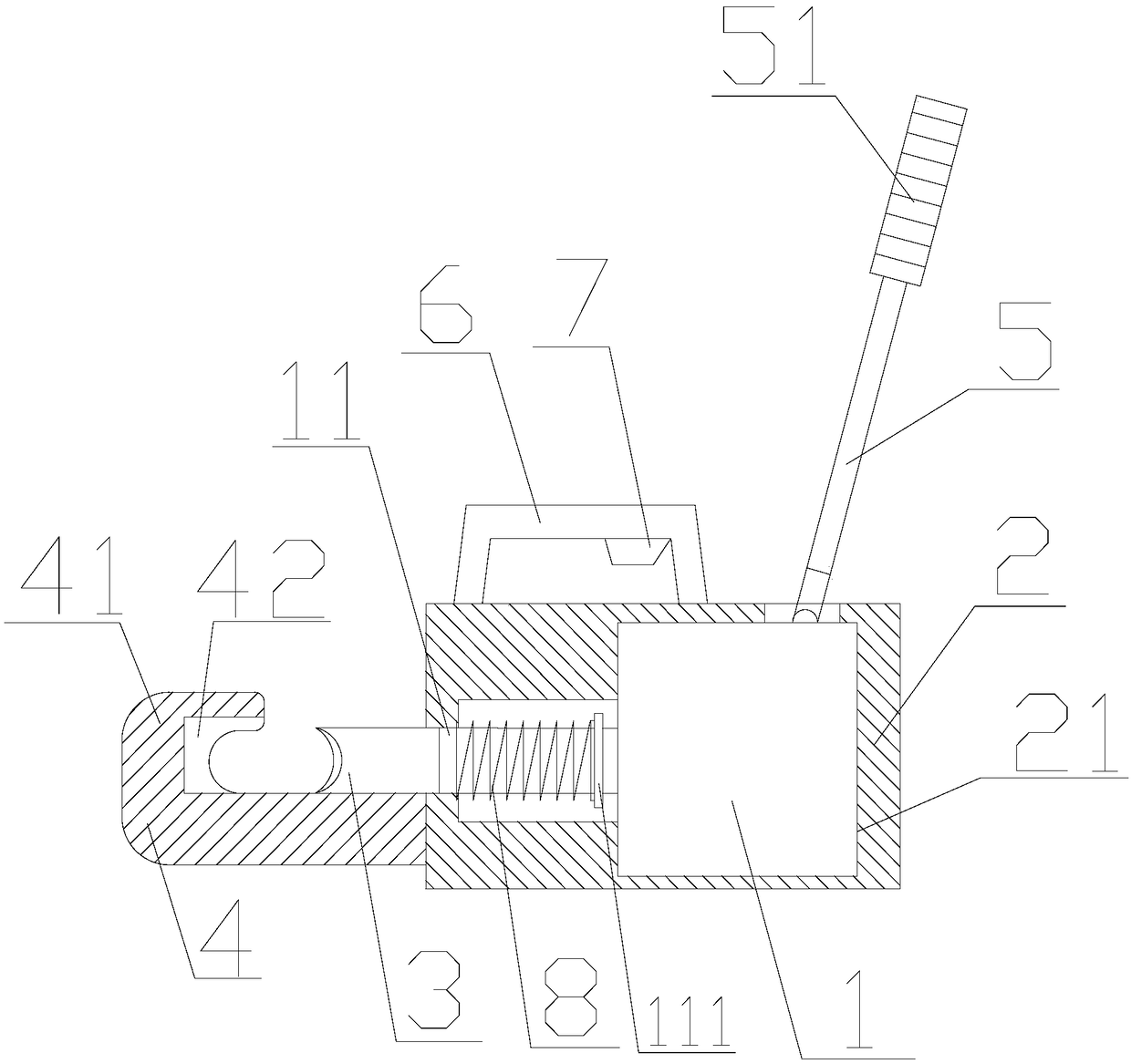
[0016] refer to figure 1 , a hydraulic shear for coaxial cable cutting according to the present invention, comprising a hydraulic cylinder 1, a main casing 2, a main blade 3, a tool holder 4, and a hydraulic cylinder rocker arm 5, and the main casing 2 is provided with a hydraulic cylinder installation cavity 21. The hydraulic cylinder installation cavity 21 is provided with a hydraulic cylinder 1, and the hydraulic cylinder 1 is provided with a telescopic arm 11, and the telescopic arm 11 extends to the outside of the main casing 2, and the telescopic arm 11 is A main blade 3 is provided, and a knife holder 4 that can cooperate with the main blade 3 is provided outside the main casing 2. The knife holder 4 and the main blade 3 form a cutting part, and the upper end of the hydraulic cylinder 1 is provided with a hydraulic pressure Cylinder rocker arm 5, the hydraulic cylinder rocker arm 5 runs through the main casing 2 and is connected to the hydraulic cylinder 1, the hydrauli...


PUM


Abstract

The invention discloses a hydraulic shear for coaxial cable cutting. The hydraulic shear for coaxial cable cutting comprises a hydraulic cylinder, a main machine shell, a main blade, a tool rest and ahydraulic cylinder rocker arm. A hydraulic cylinder mounting cavity is formed in the main machine shell. A hydraulic cylinder is arranged in the hydraulic cylinder mounting cavity. A telescopic arm is arranged on the hydraulic cylinder, the telescopic arm extends to the outside of the main machine shell, the main blade is arranged on the telescopic arm, and the tool rest which can be matched withthe main blade is arranged outside the main machine shell. The tool rest and the main blade form a cutting part, and the hydraulic cylinder rocker arm is arranged at the upper end of the hydraulic cylinder. According to the hydraulic shear for coaxial cable cutting, the hydraulic cylinder is arranged in the main machine shell, the main blade is pushed to move by the hydraulic cylinder, the circular cutting part is formed by the cooperation of the main blade and the tool rest, cables can be directly put into the cutting part, and the cables are cut by the driving force of the hydraulic cylinder. Compared with traditional technology, the hydraulic shear for coaxial cable cutting is convenient to carry, the hydraulic cylinder drives the blade to cut the cables, the cutting force is stronger,the cable cutting quality is improved, and the manpower is saved.

Description

【Technical field】 [0001] The invention relates to the technical field of cable tools, in particular to the technical field of coaxial cable cutting tools. 【Background technique】 [0002] Coaxial cable is inseparable from modern power transmission. Coaxial cable refers to a cable with two concentric conductors, and the conductor and shielding layer share the same axis. The most common coaxial cable is composed of copper wire conductors separated by insulating materials. , on the outside of the inner layer of insulation material is another layer of ring conductor and its insulator, and then the whole cable is covered by a sheath of PVC or Teflon material. The coaxial cable is divided into four layers from the inside to the outside: the central copper wire is a single-strand solid wire or multi-strand wire, a plastic insulator, a mesh conductive layer and a wire sheath, and the center copper wire and the mesh conductive layer form a current loop. It is named because the centra...

Claims


Application Information

Patent Timeline
Patent Type & Authority Applications(China)
IPC IPC(8): B21F11/00
CPCB21F11/00
Inventor 何杰
Owner 海盐明杰电子有限公司
Why Eureka
Try Eureka