Spur gear numerical control machining method

A processing method and technology of spur gears, which are applied in the field of mechanical processing, can solve problems such as tooth shape and inner hole precision error amplification, and achieve the effect of eliminating precision errors and ensuring machining accuracy

Inactive Publication Date: 2018-12-14
宁波联合蓝光科技有限公司
View PDF9 Cites 4 Cited by
  • Summary
  • Abstract
  • Description
  • Claims
  • Application Information

AI Technical Summary

Problems solved by technology

In this way, the accuracy error between the tooth shape and the inner hole and the end face will be enlarged

Method used


Image

  • Spur gear numerical control machining method
  • Spur gear numerical control machining method

Examples


Embodiment Construction

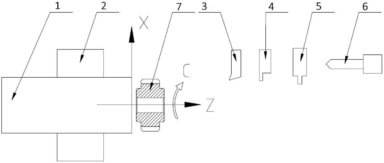
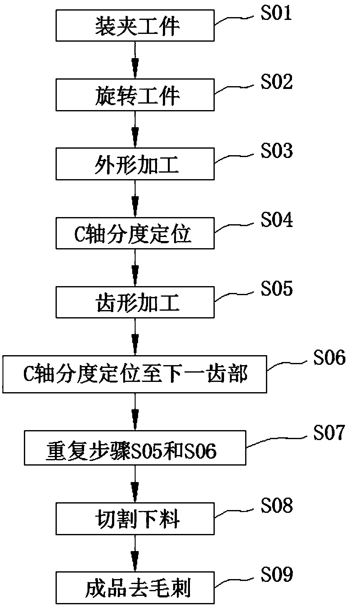
[0023] refer to figure 1 and figure 2 , the present invention provides a spur gear numerical control machining method, comprising the following steps: step S01, clamping a workpiece; clamping a bar blank 1 through a clamping device 2 of a CNC machine tool; step S02, rotating the workpiece; clamping device 2 Drive the bar blank 1 to rotate; step S03, shape processing; process the shape of the spur gear through the shape tool 3, cutting tool 4, and inner hole tool 6 of the CNC machine tool, and do not cut off the gear blank. 4 and the inner hole tool 6 to process the outline of the semi-finished gear workpiece 7; Step S04, C-axis indexing and positioning; through the C-axis function of the numerical control system, the indexing and positioning is performed, so that the bar blank 1 with the shape of the spur gear has been processed Accurately stop at the starting position of the first tooth; step S05, tooth profile processing; use the tooth profile cutter 5, and process the too...


PUM


Abstract

The invention provides a spur gear numerical control machining method. The spur gear numerical control machining method comprises the following steps that step S01, a workpiece is clamped; step S02, the workpiece is rotated; step S03, shape machining is performed; step S04, C-axis indexing positioning is performed; step S05, tooth profile machining is performed; step S06, C-axis indexing positioning is performed to a next tooth part; step S07, the step S05 and the step S06 are repeated; step S08, cutting and blanking are performed; and step S09, burrs and sharp edges of finished products are removed. The workpiece product manufactured by the spur gear numerical control machining method can eliminate the precision error problem caused by the secondary positioning clamping during the spur gear tooth profile machining, the workpiece product is machined on a CNC machine tool from the machining to the finished product blanking, midway discharging is not needed for secondary clamping machining, and the machining accuracy of the gear is ensured.

Description

technical field [0001] The invention relates to a machining method, in particular to a numerically controlled machining method for spur gears. Background technique [0002] CNC machine tool is the abbreviation of numerical control machine tool. It is an automatic machine tool equipped with a program control system. It is one of the most widely used CNC machine tools at present. The control system can logically process programs with control codes or other symbolic instructions, decode them, express them in coded numbers, and input them into the numerical control device through the information carrier. After calculation and processing, various control signals are sent by the numerical control device to control the movement of the machine tool, and the parts are automatically processed according to the shape and size required by the drawing. CNC machine tools solve complex, precise, small-batch, and multi-variety parts processing problems. It is a flexible, high-efficiency aut...

Claims


Application Information

Patent Timeline
Patent Type & Authority Applications(China)
IPC IPC(8): B23P15/14
CPCB23P15/14
Inventor 季永生凌峰陈学军
Owner 宁波联合蓝光科技有限公司
Why Eureka
Try Eureka