
Built-in engine sump tank heater

An engine oil, built-in technology, used in oil pans, engine components, machines/engines, etc., can solve the problems of limited heating area, poor heating effect, and small size of the heater, so as to improve heating efficiency and facilitate smooth operation. Activate, increase the effect of contact area

Pending Publication Date: 2018-12-14
山东宇升电子科技有限公司
View PDF16 Cites 0 Cited by
  • Summary
  • Abstract
  • Description
  • Claims
  • Application Information

AI Technical Summary

Problems solved by technology

[0003] Existing heaters are designed to improve the oil operating environment of winter cars, but the heaters are mostly installed on the outer bottom of the oil pan for heating. For example, the heater adopts a ceramic thermistor heating element and is installed on the bottom of the oil pan. The preheater adopts the preheating tube installed at the bottom of the oil pan, the preheating tube is connected to the output end of the inverter, and the heater is connected to the power supply to heat the oil pan, thereby heating the oil inside the oil pan. Although it can achieve a certain heating effect, because the heater is installed outside the oil pan, the heater cannot directly contact the oil and needs heat conduction to heat the oil, so the heating effect is not good, the heating time is long, and the energy consumption is high; in addition , the heater is designed as an internal resistance wire and an external bolt-shaped shell. This kind of heater is small in size and can be placed in the oil pan. However, due to the small size of the heater and its limited heating area, the heating effect is often not good.

Method used


Image

  • Built-in engine sump tank heater
  • Built-in engine sump tank heater
  • Built-in engine sump tank heater

Examples


Embodiment Construction

[0039] The principles and features of the present invention are described below in conjunction with examples, which are only used to explain the present invention and are not intended to limit the scope of the present invention.

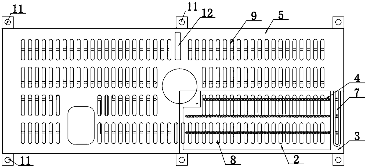
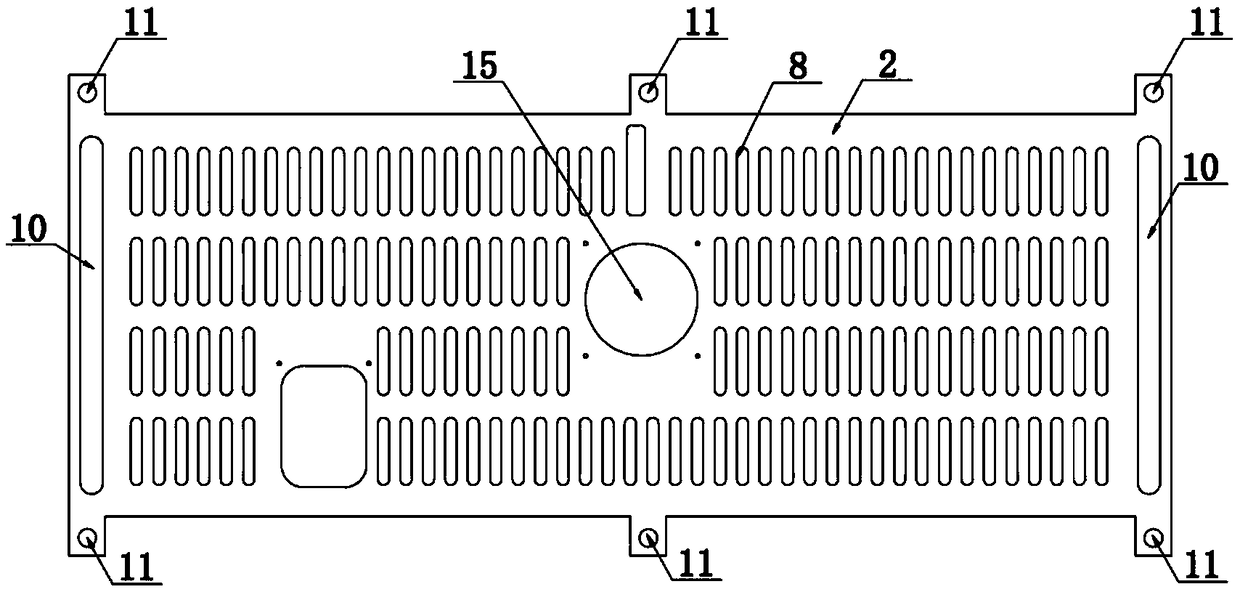
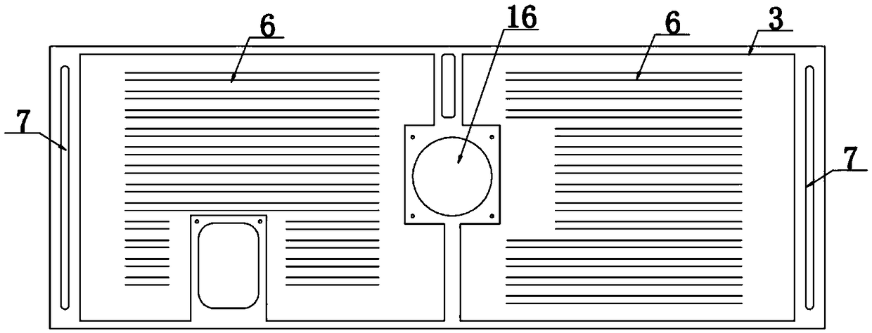
[0040] like Figure 1-7 As shown, a built-in engine oil pan heater includes a heating plate arranged in the oil pan, the heating plate includes a bottom plate 2, an inner tank 3, a heating element 4 and a cover plate 5, and the heating element is installed On the inner container, the inner container is arranged between the bottom plate and the cover plate, and the two ends of the inner container are provided with wiring boards 7 for connecting the heating element with a power supply.

[0041] The heating element can adopt a heating wire whose publication number is CN102281655A. This heating wire is not only safe to use, not easy to wear, ensures the heating effect of fuel oil, but also saves electric energy and is more environmentally friendly.

[0...


PUM


Abstract

The invention discloses a built-in engine sump tank heater, and belongs to the technical field of engines. The built-in engine sump tank heater comprises a heating plate, wherein the heating plate comprises a bottom plate, an inner container, a heating workpiece and a cover plate; the heating workpiece is arranged on the inner container; the inner container is arranged between the bottom plate andthe cover plate; a heat conducting groove for placing the heating workpiece is arranged in the inner container; and wiring plates for communicating the heating workpiece and a power supply are arranged at two ends of the inner container. A bottom plate through hole is formed in the bottom plate; and an inner container through hole and a cover plate through hole are formed in the positions, corresponding to the bottom plate through hole, in the inner container and the cover plate. The heater is built in, so that the heat conducting time is shortened; the heater adopts the heating plate, the heating area of the heating plate is large, and the heater can be arranged according to the difference of oil sump appearance structures, so that the contact area of the heating workpiece and engine oilis increased, heat can be quickly recycled, and the heating efficiency is improved; and automobile engine oil is fast in heating, and after automobile engine oil is heated, the motor speed is normal,so that an automobile can be smoothly started up.

Description

technical field [0001] The invention relates to a built-in engine oil pan heater, which belongs to the technical field of engines. Background technique [0002] There are two main reasons why the vehicle is not easy to start in winter: 1. The temperature of the fuel is too low. Because diesel is compression ignited, the compression ratio needs to be increased in winter. The source of the compression ratio is determined by the speed of the starter motor. Due to the solidification of the engine oil in winter, the speed of the motor will drop, resulting in the compression ratio not increasing, and the vehicle is difficult to start. 2. In order for the starter to reach the predetermined speed, it is necessary to heat the oil in the oil pan. [0003] Existing heaters are designed to improve the oil operating environment of winter cars, but the heaters are mostly installed on the outer bottom of the oil pan for heating. For example, the heater adopts a ceramic thermistor heating ...

Claims


Application Information

Patent Timeline
IPC IPC(8): F01M5/02F01M11/00
CPCF01M5/021F01M11/0004F01M2005/023F01M2011/0025
Inventor 孙伟孙靖茗
Owner 山东宇升电子科技有限公司
Learn More