
Fan speed-adjusting circuit

A speed regulation and circuit technology, which is applied in pump control, non-variable pumps, machines/engines, etc., can solve the problems of large voltage instability error, limited working voltage, and high input voltage, and achieve accurate speed regulation voltage Stable, large adjustable voltage range, and stable feedback voltage

Pending Publication Date: 2018-12-14
GUANGZHOU PENGLIN LIGHTING CO LTD
View PDF0 Cites 0 Cited by
  • Summary
  • Abstract
  • Description
  • Claims
  • Application Information

AI Technical Summary

Problems solved by technology

[0004] There are mainly three kinds of fan speed regulation circuits currently in use: the first one is controlled by a single triode plus PWM signal. Large stability error and other problems; the second one adds comparator and feedback signal plus triode analog signal control to stabilize the voltage, but due to analog signal control and linear constant voltage, this circuit has low efficiency and serious heating of components, and the input voltage The higher the efficiency, the lower the heat, the more serious the heat, so the design is limited by the input voltage and the fan operating voltage; the third is that the fan manufacturer needs to add a speed regulation circuit inside the fan to leave a PWM interface for the MCU to control. The fan itself There is no constant voltage function, so the input voltage cannot be higher than the working voltage of the fan, and the cost of the fan itself is increased. If you need to input a voltage higher than the fan, you need to add a constant voltage circuit, which increases the cost

Method used


Image

  • Fan speed-adjusting circuit

Examples


Embodiment Construction

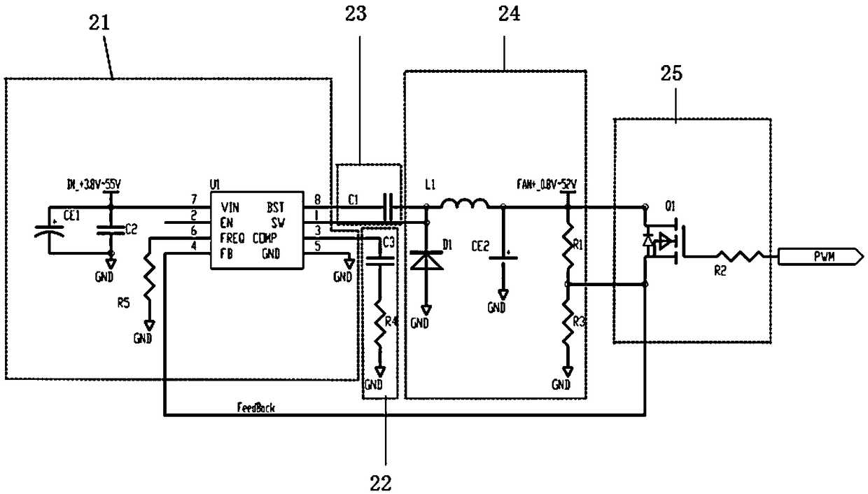
[0015] Such as figure 1 As shown, a fan speed regulation circuit disclosed in the present invention is a complete high-efficiency switch-type constant voltage PWM fan speed regulation application solution. Including switching power supply 21, compensation circuit 22, drive circuit 23, constant voltage system 24, regulation system 25, said switching power supply 21, compensation circuit 22, drive circuit 23, constant voltage system 24, regulation system 25 are electrically connected.

[0016] The switching power supply 21 includes a DC-DC switch type constant voltage chip U1 and a resistor R5. The EN pin 2 of the DC-DC switch type constant voltage chip U1 is suspended, the GND pin 5 is grounded, and the VIN pin 7 is connected to the input voltage, and then through the circuit It is connected with other components and used as an adjustable output power supply to provide voltage for the entire circuit. The switching frequency of the DC-DC switching constant voltage chip U1 can be...


PUM


Abstract

The invention relates to the field of stage lamp heat dissipation and discloses a fan speed-adjusting circuit. The fan speed-adjusting circuit comprises a switching power supply, a compensating circuit, a driving circuit, a constant voltage system and an adjusting system, wherein the switching power supply, the compensating circuit, the driving circuit, the constant voltage system and the adjusting system are connected through circuits. By means of the fan speed-adjusting circuit, heating of components can be reduced, various fans with the different specifications are controlled, limit of input voltage and fan working voltage is avoided, the service life of a fan is prolonged, and meanwhile the noise is lowered.

Description

technical field [0001] The invention relates to the field of stage lamp heat dissipation, in particular to a fan speed regulating circuit. Background technique [0002] As the application of stage lamps becomes more and more frequent, the heat dissipation problem of stage lamps becomes more and more prominent. Fans, as an effective cooling tool, have been widely used. [0003] The earliest stage lighting did not have a control circuit when using a fan to dissipate heat. As long as the fan was turned on, the fan would keep running, which would lead to a short life of the fan. Later, it was developed to only have a switch control circuit, that is, the fan can only be controlled to be in two states of on or off. This situation still cannot meet the actual use requirements. The inability to control the fan speed leads to high noise and affects the use environment. In recent years, cooling fans have gradually added speed regulation functions. [0004] There are mainly three ki...

Claims


Application Information

Patent Timeline
IPC IPC(8): F04D27/00
CPCF04D27/004
Inventor 陈小聪
Owner GUANGZHOU PENGLIN LIGHTING CO LTD
Features
  • Generate Ideas
  • Intellectual Property
  • Life Sciences
  • Materials
  • Tech Scout
  • Unparalleled Data Quality
  • Higher Quality Content
  • 60% Fewer Hallucinations
Learn More