A self-energizing system and method of operation

A working method and self-powered technology, applied in the field of energy management, to achieve the effect of improving efficiency, ultra-low power consumption, and extending the working cycle

Active Publication Date: 2018-12-14
UNIV OF ELECTRONICS SCI & TECH OF CHINA
View PDF6 Cites 9 Cited by
  • Summary
  • Abstract
  • Description
  • Claims
  • Application Information

AI Technical Summary

Problems solved by technology

Such an adaptive energy management method for energy collection and energy consumption can realize the requirement of rapidly increasing the energy accumulation speed under the condition of small system size and extremely low cost, and use energy as much as possible to realize load function tasks , improve the efficiency of energy utilization

Method used


Image

  • A self-energizing system and method of operation
  • A self-energizing system and method of operation
  • A self-energizing system and method of operation

Examples


Embodiment 1

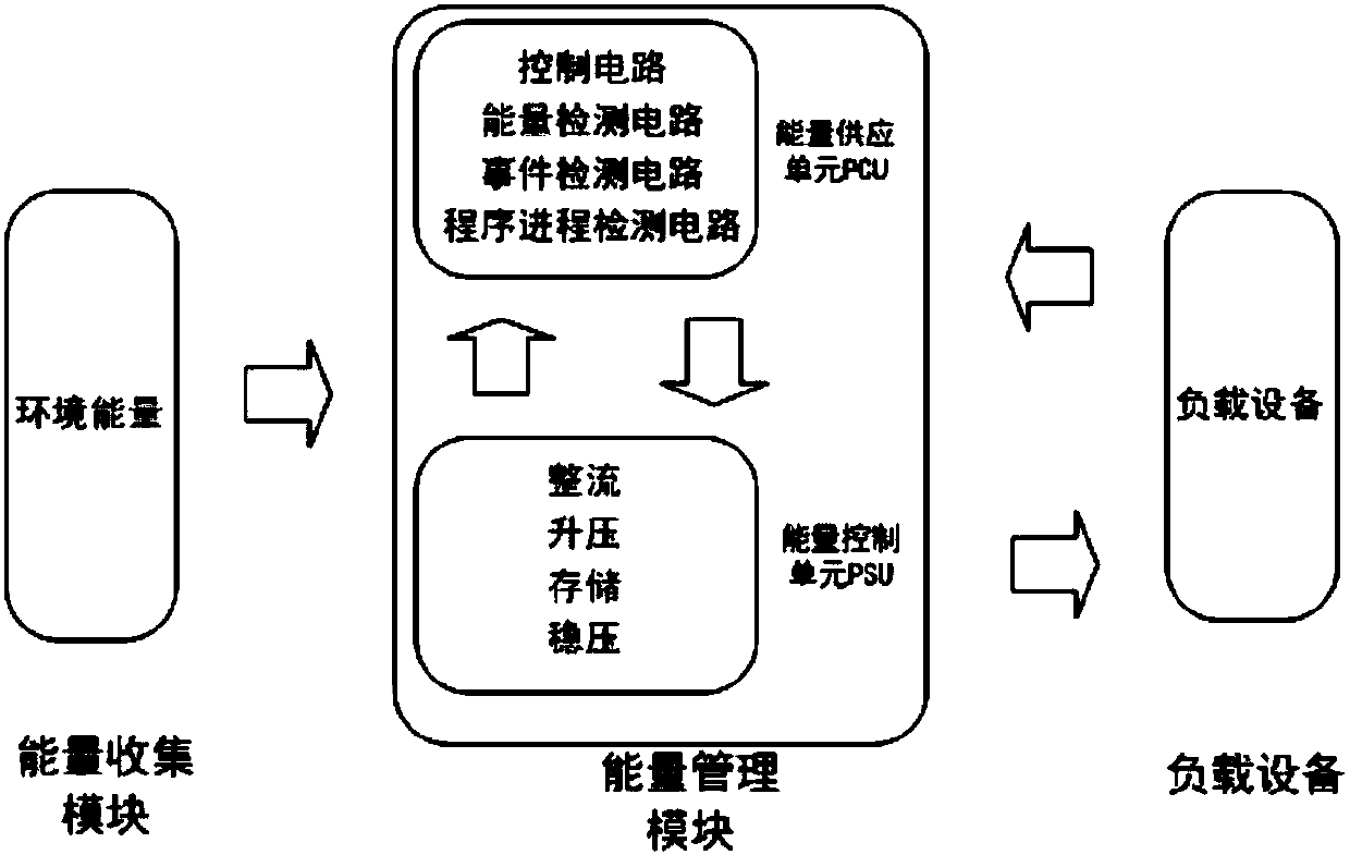
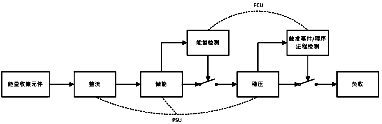
[0046] Such as figure 1 As shown, Embodiment 1 is a self-energy supply system, which includes an energy harvesting module (EnergyHarvestingModule, EHD) and an energy management module (PowerManagementModule, PMM), and the energy harvesting module is connected to the load device through the energy management module, Thereby providing working energy to the load equipment.

[0047] The energy harvesting module (Energy Harvesting Module, EHD) is used to collect environmental energy and convert the environmental energy into electrical energy for output. The environmental energy includes but not limited to human body motion energy, temperature difference, solar energy, wind energy, radiation, etc. In one embodiment, the energy harvesting device collects the pressure generated by various mechanical actions as a non-electrical signal and converts it into electrical energy for output. The corresponding energy harvesting module is a piezoelectric energy harvesting device.

[0048] Sinc...

Embodiment 2

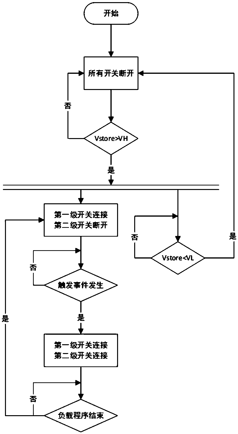
[0057] Such as figure 2 , the present embodiment is a working method of a self-powered system, the self-powered system is but not limited to any one of the aforementioned self-powered systems, and the working method of the self-powered system includes the following steps:

[0058] S1, system initialization. In the initialization state, the entire self-powered system is in the state of power exhaustion. The system does not have any external components that can directly provide power. The energy control unit PCU is in a power-off state, and the load device and the energy management module are connected disconnection between

[0059] S2, the energy collection module starts to work, collects the external environmental energy, and the non-electrical signal of the collected environmental energy is converted and output to the energy management module as electric energy;

[0060] S3, after the energy management module receives the electric energy transmitted by the energy harvesting...


PUM


Abstract

The invention discloses a self-energizing supply system and a working method of the system, which relates to the field of energy management. The self-power supply system comprises an energy collectionmodule and an energy management module. The energy collection module is connected with the load device through the energy management module so as to provide working energy to the load device. The energy collecting module is used for collecting environmental energy and outputting the environmental energy after converting the environmental energy into electric energy; The energy management module is used for receiving electric energy output from the energy collection module and outputting stable electric energy to power consumption circuits at various levels according to the configuration of the system and the requirements of energy consumption at various levels. The load device includes at least one energy dissipating element of a sensor, a processor, a communication module, or a communication device for performing respective circuit functions. The scheme provided by the invention can realize the complete self-supply of energy and does not need an external spare battery. It can judge the switch intelligently and adjust the load cycle adaptively, and has the characteristics of ultra-low power consumption.

Description

technical field [0001] The invention relates to the field of energy management, in particular to a fully self-powered electrical system and a system working method. Background technique [0002] In recent years, self-energy technology has developed rapidly. There are many different self-energy technologies in the existing technology that can convert environmental energy, such as kinetic energy, light energy, electromagnetic radiation, temperature change (temperature difference), human body motion energy, vibration source, etc., into electrical energy. Self-powered technology is widely used in circuit system design where energy is limited and long life is required, such as the power supply of miniature sensors. For most environments, energy has the characteristics of low energy density, and it also needs to cooperate with a dedicated energy management method for energy harvesting to quickly accumulate power to provide stable power supply. In literature [1], a DC-DC boost co...

Claims


Application Information

Patent Timeline
Patent Type & Authority Applications(China)
IPC IPC(8): H02J3/00
CPCH02J3/00
Inventor 张岩黄瑞
Owner UNIV OF ELECTRONICS SCI & TECH OF CHINA
Why Eureka
Try Eureka