
Method for simply controlling arrangement direction of laser-induced surface periodic structure

A periodic structure and laser-induced technology, applied in the field of laser applications, can solve problems such as high cost, complicated operation, and complicated process, and achieve the effects of simple control, improved processing efficiency, and reduced processing cost

Active Publication Date: 2018-12-18
BEIJING INSTITUTE OF TECHNOLOGYGY
View PDF6 Cites 7 Cited by
  • Summary
  • Abstract
  • Description
  • Claims
  • Application Information

AI Technical Summary

Problems solved by technology

However, the above-mentioned method is relatively complicated to operate, and requires a complex rotation control device and computer programming, which is costly and complicated. Therefore, a processing method that is easy to operate and does not require a complicated rotation control device is required.

Method used


Image

  • Method for simply controlling arrangement direction of laser-induced surface periodic structure
  • Method for simply controlling arrangement direction of laser-induced surface periodic structure
  • Method for simply controlling arrangement direction of laser-induced surface periodic structure

Examples


Embodiment 1

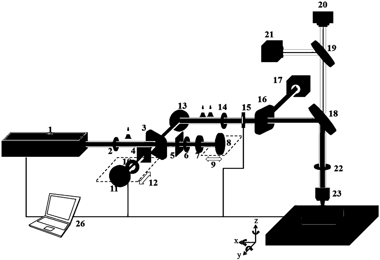
[0027] Taking the method of the present invention to process a periodic structure with a linear path perpendicular to the scanning direction on the surface of the Si material as an example, use such as figure 1 The light path structure shown, the specific equipment used is as follows:

[0028] The femtosecond laser 1 used in this embodiment is a laser produced by Spectrum Physics, with a laser center wavelength of 800 nm, a pulse width of 50 fs, a maximum repetition frequency of 1 KHz, a single pulse maximum energy of 3 mJ, and a Gaussian light intensity distribution. The exit laser is horizontally polarized.

[0029] The structure of the Michelson interferometer consists of the following parts: a first beam splitter 3, a first mirror 8, a second mirror 11, a manual mechanical translation stage 9, and an electromechanical translation stage 12. The manual mechanical translation stage 9 is adjusted to make the two sub-pulses zero delay, and the electromechanical translation stage 12 ...

Embodiment 2

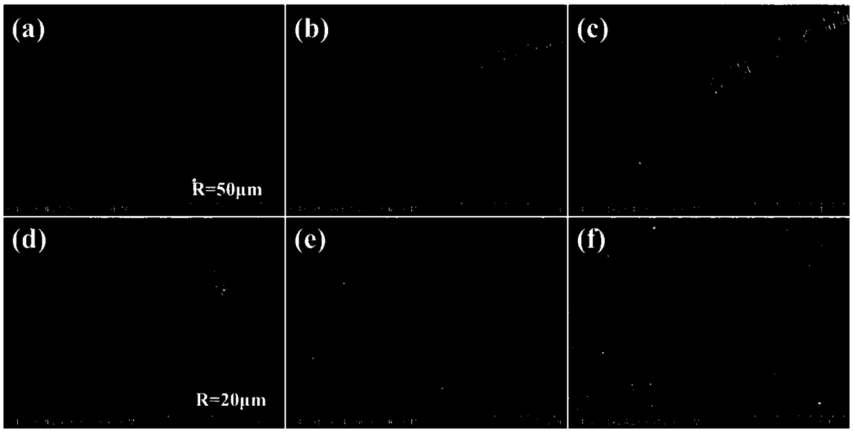
[0040] The other steps are the same as in embodiment 1, the difference is: in step (4), the scanning path is no longer a straight line, but a circular path with a radius of 50μm and 20μm. The structure arrangement direction is perpendicular to the scanning direction. Periodic structure, such as image 3 Shown.

Embodiment 3

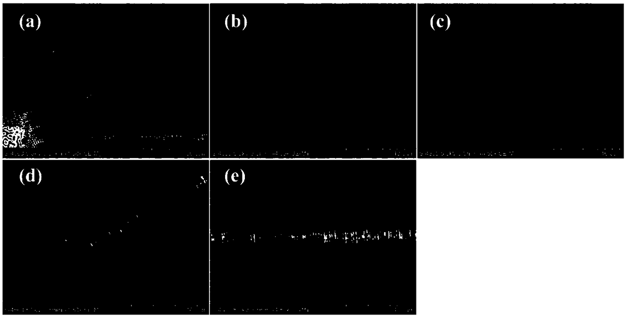
[0042] The other steps are the same as in embodiment 1, the difference is: in step (4), the scanning path is no longer a straight line but a sinusoidal path, and the periodic structure of the sinusoidal path with the structure arrangement direction perpendicular to the scanning direction is obtained, such as Figure 4 Shown.


PUM

PropertyMeasurementUnit
diameteraaaaaaaaaa

Abstract

The invention relates to a method for simply controlling an arrangement direction of a femtosecond laser-induced surface periodic structure to be perpendicular to a scanning direction based on electronic dynamic control, and belongs to the technical field of laser application. The method comprises the following steps of: utilizing a femtosecond laser unit to generate femtosecond laser single pulse; utilizing a combined light path for an Michelson interferometer structure and a quarter-wave plate for converting femtosecond laser single pulse into femtosecond laser double pulses with mutually perpendicular polarization directions, and focusing perpendicularly polarized femtosecond laser double pulses to a to-be-processed material surface through an optical objective lens; and controlling a to-be-processed material to move according to set moving speed and a set moving path, thereby processing out the periodic structure mutually perpendicular to the scanning direction on the material surface. Compared with the prior art, the method does not need a complex rotation control device and a complex computer program design, and only needs to change the scanning direction for realizing simplecontrol on the arrangement direction of the femtosecond laser-induced surface periodic structure, so that the processing cost is reduced, and processing efficiency is improved.

Description

Technical field [0001] The invention relates to a method for simply controlling the arrangement direction of a periodic structure on a submicron surface induced by a femtosecond laser, and belongs to the technical field of laser application. Background technique [0002] Femtosecond laser-induced periodic surface structure has good optical, electrical and wettability characteristics, and has a wide range of applications in structural color, surface enhanced Raman, photovoltaic and other fields. For sub-wavelength femtosecond laser-induced periodic structures on the surface, the arrangement direction is generally perpendicular to the laser polarization direction. In the process of femtosecond laser direct writing, it is often necessary to change the direction of the obtained periodic structure. The usual practice is to install a half-wave plate on the optical path and change the polarization direction of the femtosecond laser by rotating the half-wave plate. Change the direction ...

Claims


Application Information

Patent Timeline
Patent Type & Authority Applications(China)
IPC IPC(8): B23K26/00B23K26/70
CPCB23K26/00B23K26/704
Inventor 姜澜刘威胡洁
Owner BEIJING INSTITUTE OF TECHNOLOGYGY
Learn More