
Polishing device and polishing method for ultra-smooth surfaces of optical elements

A technology of ultra-smooth surface and polishing device, which is applied in the processing device of used abrasives, grinding/polishing equipment, abrasives, etc., can solve the problems of low polishing efficiency and achieve improved processing efficiency, low processing accuracy requirements, and equipment low cost effect

Inactive Publication Date: 2018-12-18
XIAN TECHNOLOGICAL UNIV
View PDF4 Cites 2 Cited by
  • Summary
  • Abstract
  • Description
  • Claims
  • Application Information

AI Technical Summary

Problems solved by technology

[0006] The present invention provides an optical element ultra-smooth surface polishing device and polishing method to overcome the low polishing efficiency in the prior art, the need for high-precision CNC machine tool control, and the large-area removal of waviness errors

Method used

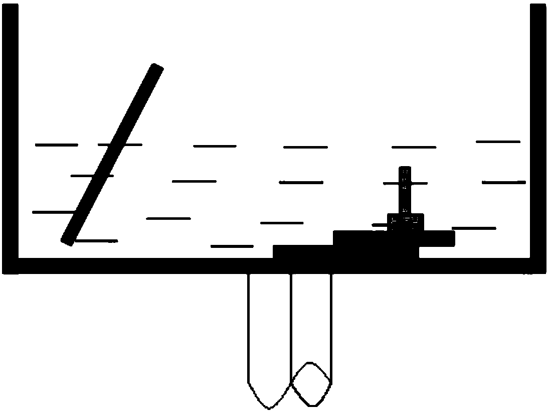
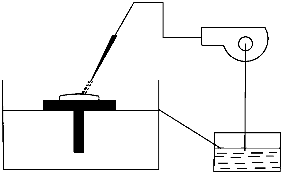
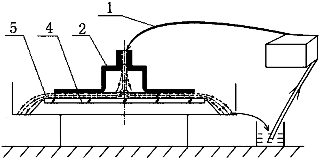

Image

  • Polishing device and polishing method for ultra-smooth surfaces of optical elements
  • Polishing device and polishing method for ultra-smooth surfaces of optical elements
  • Polishing device and polishing method for ultra-smooth surfaces of optical elements

Examples


Embodiment 1

[0034] A polishing device for an optical element ultra-smooth surface (see image 3 ), which is an axisymmetric structure, including a pipeline 1 and a grinding head 2 for liquid supply in the middle, the polishing surface of the lower end of the grinding head 2 is a plane, and several annular grooves are arranged at equal intervals along the center of the circle on the polishing surface. The cross section of the groove is arc-shaped, and the annular grooves are distributed on the outer circle of the polishing surface.

[0035] A polishing method for a polishing device with an ultra-smooth surface of an optical element. The pipeline transports the polishing liquid to the center of the grinding head. The polishing liquid is a Newtonian fluid. Under the action of pressure, the polishing liquid flows from the center of the grinding head to the surroundings. A liquid film is formed between the polishing surface of the grinding head and the workpiece 4 to isolate the grinding head ...

Embodiment 2

[0040] This embodiment improves the structure of the grinding head. Since the gravity of the grinding head is a variable based on the initial structure of the grinding head, it is necessary to change the gravity of the weight added to the grinding head to adjust, so the grinding head can be designed as a general purpose The universal joint structure can pressurize the grinding head through air pressure, such as Figure 15 As shown, the polishing fluid enters the grinding head from the symmetrical inlets on both sides. Through the grinding head, the workpiece is removed. The removal mechanism is the same as above. The pressure adjustment of the air pressure can control the gravity of the grinding head between 20kg~60kg, that is, the approximate adjustment range of the corresponding air pressure is: 0.15MPa~0.6MPa.


PUM

PropertyMeasurementUnit
densityaaaaaaaaaa

Abstract

The invention relates to the technical field of ultra-smooth surface polishing of optical elements, in particular to a polishing device and a polishing method for the ultra-smooth surfaces of the optical elements. The problems of low polishing efficiency, needing of control by a high-precision numerical control machine tool and wave degree error caused by large-area removal in the prior art are solved. The polishing device is of an axisymmetric structure and comprises a pipeline and a grinding head for supplying liquid in the middle, wherein the polishing surface at the lower end of the grinding head is a plane, and a plurality of annular grooves are formed at equal intervals in the polishing surface along the center of a circle; the annular grooves are distributed at the outer circle of the polishing surface, and the pipeline conveys polishing liquid to the center of the grinding head; the polishing liquid is Newtonian fluid, and under the action of pressure, the polishing liquid flows from the center of the grinding head to the periphery to form a liquid film between the polishing surface of the grinding head and a workpiece to separate the grinding head from the workpiece; and the grinding head floats on the surface of the workpiece, the fluid flows through a polishing area to form eddy current at the grooves of the polishing surface and obliquely enters and shoots on the surface of the workpiece, a shearing force is generated on the surface of the workpiece, and material removal is realized.

Description

Technical field: [0001] The invention relates to the technical field of polishing the ultra-smooth surface of an optical element, in particular to a polishing device and a polishing method for an ultra-smooth surface of an optical element. Background technique: [0002] In recent years, optical components have been used more and more widely in aerospace, national defense, nuclear energy industry, astronomical detection, optoelectronic industry and other fields, especially for optical components used in short-wave ultraviolet light and strong laser, which have a great impact on the surface shape and roughness of optical components. For example, the roughness index of traditional optical components has developed from more than a dozen nanometers to less than 1 nanometer, that is, the ultra-smooth surface processing of optical components. [0003] At present, the main methods used in the ultra-smooth surface processing technology of optical components are: bath polishing, ultra...

Claims


Application Information

Patent Timeline
Patent Type & Authority Applications(China)
IPC IPC(8): B24C1/08B24C3/04B24C5/00B24C9/00
CPCB24C1/08B24C3/04B24C5/00B24C9/00
Inventor 弥谦李宏郭忠达潘永强秦琳
Owner XIAN TECHNOLOGICAL UNIV
Learn More