A method for increasing the scattering angle of the short-axis scattering direction of anisotropic light-scattering materials

An anisotropic and directional scattering technology, applied in the field of polymer-based composite material preparation technology, can solve the problems of small scattering angle and shrinking scattering angle, and achieve the effect of large scattering angle

Active Publication Date: 2020-12-11
SICHUAN UNIV
View PDF6 Cites 0 Cited by
  • Summary
  • Abstract
  • Description
  • Claims
  • Application Information

AI Technical Summary

Problems solved by technology

This preparation method can prepare light-scattering materials with different degrees of anisotropy by adjusting the degree of orientation deformation of polymer scatterers, but this type of light-scattering materials: 1, can only produce a single light scattering effect, and the scattering angle is small; While increasing the scattering angle in the y-direction (long-axis scattering direction), the scattering angle in the x-direction (short-axis scattering direction) will be greatly reduced

Method used


Image

  • A method for increasing the scattering angle of the short-axis scattering direction of anisotropic light-scattering materials
  • A method for increasing the scattering angle of the short-axis scattering direction of anisotropic light-scattering materials

Examples


Embodiment 1

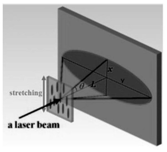
[0037] 70 parts by mass of polycarbonate (PC), 30 parts by mass of acrylonitrile copolymer (SAN) and 1.7%, 3.3%, 5.0%, 6.7% of the total weight of SAN, respectively, polymethylsilsesquioxane with a diameter of 10um Polycarbonate beads (OSB3) were melted and blended by a torque rheometer, and granulated to obtain polycarbonate composite particles. The composite particles were molded at 240°C into 100.0mm (length) × 30.0mm (width) × 1mm ( thick) samples. Then the sample was fixed in a high-temperature universal tensile testing machine and thermally stretched at 190°C with a stretch ratio of 2. The scattering angles in the short-axis scattering direction (x direction) are 18.7º, 20.1º, 20.8º, 22.0º, respectively, and the scattering angles in the long-axis scattering direction (y direction) are 30.2º, 30.9º, 31.0º, 32.3º, respectively. .

Embodiment 2

[0039] 30 parts by mass of acrylonitrile copolymer (SAN) were mixed with 1.7%, 3.3%, 5.0%, and 6.7% of the total weight of SAN with nano-calcium carbonate (nano-CaCO3) after surface treatment with a silane coupling agent. 3 ) was extruded at 200°C with a micro-blending extrusion rheometer, pelletized, and the pelletized SAN / nano-CaCO 3 The blend and 70 parts by mass of polycarbonate (PC) were melt-blended in a torque rheometer and granulated at a temperature of 240°C to obtain polycarbonate composite particles. The composite particles were heated at 240°C Molded into a sample of 100.0mm (length) × 30.0mm (width) × 1mm (thickness). Then the sample was fixed in a high-temperature universal tensile testing machine and thermally stretched at 190°C with a stretch ratio of 2. The scattering angles in the short-axis scattering direction (x direction) were measured to be 33.2º, 35.9º, 39.9º, 41.1º, and the scattering angles in the long-axis scattering direction (y direction) were 55....

Embodiment 3

[0041]70 parts by mass of polycarbonate (PC), 30 parts by mass of acrylonitrile copolymer (SAN) and 3.3% of the total weight of SAN polymethylsilsesquioxane beads (OSB1) with a diameter of 2um were subjected to torque flow Polycarbonate composite particles were obtained by melt blending and granulation, and the composite particles were molded at 240°C into a sample of 100.0 mm (length) × 30.0 mm (width) × 1 mm (thickness). Then the samples were fixed in a high-temperature universal tensile testing machine and thermally stretched at 190°C, and the stretching ratios were 2 and 2.5, respectively. It is measured that the scattering angles in the short-axis scattering direction (x direction) are 27.4º and 23.8º, and the scattering angles in the long-axis scattering direction (y direction) are 33.4º and 31.0º.


PUM

PropertyMeasurementUnit
particle diameteraaaaaaaaaa
heat deflection temperatureaaaaaaaaaa

Abstract

The invention provides a method for increasing a scattering angle of a short-axis scattering direction of an anisotropic light-scattering material. The method is characterized in that both a substrateof the light-scattering material and a first scatterer are transparent polymers, particles having a smaller particle size are introduced into the polymer scatterer as a second scatterer, a compositescatterer having a complex eye structure is formed, a first scatterer is big eye, and the second scatterer is small eye. The anisotropy is achieved by controlling the orientation deformation of the big-eye scatterer in the substrate by controlling a tensile force field of a polymer melt; the small eye scatterer is selectively distributed in the big eye scatterer or at an interface of the big eye scatterer and the substrate, and the scattering angle of the short-axis scattering direction is increased by the multiple scattering action of the complex eye scatterer.

Description

technical field [0001] The invention belongs to the field of preparation technology of polymer-based composite materials, and in particular relates to a method for increasing the scattering angle in the short-axis scattering direction of anisotropic light-scattering materials. Its feature is that the first scatterer of the composite scatterer that constitutes a "compound eye" structure is easy to deform, and the second scatterer is not easily deformed. The anisotropic light-scattering material can be prepared by adjusting the shape of the first scatterer by thermo-stretch molding, flat die extrusion molding, extrusion-multistage stretch molding, blow molding or injection molding. When the shape of the first scatterer changes, the relative position of the second scatterer distributed in the first scatterer or at the interface with the substrate will also change accordingly. In this way, the effect of not excessively losing the scattering angle in the other direction can be ach...

Claims


Application Information

Patent Timeline
Patent Type & Authority Patents(China)
IPC IPC(8): C08L69/00C08L33/20C08L83/04C08K9/06C08K3/26G02B5/02
CPCC08K2003/265C08K2201/011C08L69/00C08L2205/03C08L2205/18G02B5/0242G02B5/0257G02B5/0278C08L33/20C08L83/04C08K9/06C08K3/26
Inventor 熊英丁奕同郭少云赵梓汝
Owner SICHUAN UNIV
Why Eureka
Try Eureka