Eureka AIR delivers breakthrough ideas for toughest innovation challenges, trusted by R&D personnel around the world.

Top drive control system

A control system and top drive technology, which is applied to the automatic control system of drilling, directional drilling, rotary drilling, etc., can solve the problem that the sliding drilling system cannot realize the switching of top drive control signals, and can not further eliminate the static friction of the drill string. Complicated issues

Inactive Publication Date: 2018-12-18
CHINA NAT PETROLEUM CORP CHUANQING DRILLING ENG CO LTD +1
View PDF11 Cites 7 Cited by
  • Summary
  • Abstract
  • Description
  • Claims
  • Application Information

AI Technical Summary

Problems solved by technology

[0007] However, the existing sliding drilling control system represented by the above-mentioned patent documents has a relatively complicated structure, and the sliding drilling system cannot realize the switching of the top drive control signal, and cannot realize the forward and reverse rotation of the drill string.
Just can't further eliminate the static friction of whole drill string, ROP and efficiency can't be further improved

Method used


Image

  • Top drive control system
  • Top drive control system

Examples


Embodiment 1

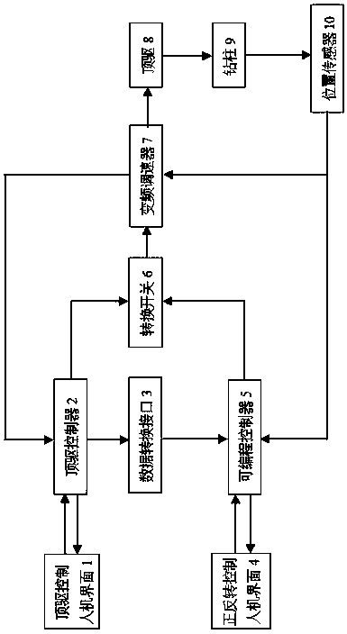
[0037] As a preferred embodiment of the present invention, it discloses a top drive control system, which includes a top drive control man-machine interface, a top drive controller 2, a data conversion interface 3, and a forward and reverse control man-machine interface 4, which can Programmable controller 5, transfer switch 6, frequency converter 7, top drive 8, drill string 9 and position sensor 10, the man-machine interface for the top drive control is installed on the top drive controller 2, and the top drive controller 2 passes through The cable is connected to the transfer switch 6; the forward and reverse control man-machine interface 4 is connected to the programmable controller 5, and the programmable controller 5 is connected to the transfer switch 6 through a cable; the top drive controller 2 is connected to the programmable controller through the data conversion interface 3 The programming controller 5 is connected; the other end of the transfer switch 6 is connecte...

Embodiment 2

[0039] On the basis of Example 1, as another preferred embodiment of the present invention, as shown in the attached drawings, the present invention includes a top drive control man-machine interface, a top drive controller 2, a data conversion interface 3, front and back Turn control man-machine interface 4, programmable controller 5, transfer switch 6, frequency conversion governor 7, top drive 8, drill string 9 and position sensor 10.

[0040] In the case of compound drilling or sliding drilling without "support pressure", the operator inputs commands through the top drive control man-machine interface, and the top drive control man-machine interface converts the command into a specific data format through the internal microprocessor. The serial port, network card or USB port transmits the data to the top drive controller 2, and the top drive controller 2 calculates through the internal arithmetic unit to obtain the control signal to control the frequency converter 7, and th...

Embodiment 3

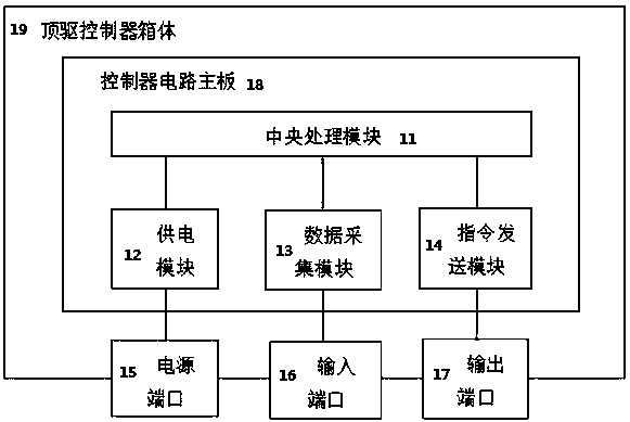
[0046] As the best embodiment of the present invention, on the basis of Embodiment 2, the top drive controller 2 adopted includes a central processing module 11, a power supply module 12, a data acquisition module 13, an instruction sending module 14, a power port 15, an input Port 16, output port 17, controller circuit board 18, top drive controller box 19. The central processing module 11 , the power supply module 12 , the data acquisition module 13 and the instruction sending module 14 are installed on the controller circuit main board 18 . The power port 15 , input port 16 and output port 17 are installed on the top drive controller box 19 .

[0047] The power supply port 15 is connected to the power supply module 12. Under normal operation, the power supply module 12 is charged by an external power supply connected to the power supply port 15, and at the same time drives the operation of the circuit elements in the entire control box. Start the emergency power supply and...


PUM


Abstract

The invention discloses a top drive control system, and relates to the technical field of automatic control of petroleum drilling. The top drive control system comprises a top drive control human-computer interface, a top drive controller, a data conversion interface, a forward and reverse rotation control human-computer interface, a programmable controller, a change-over switch, a variable-frequency speed regulator, a top drive, a drill column and a position sensor, the top drive control human-computer interface is installed on the top drive controller, the top drive controller is connected with the change-over switch through a cable, and the forward and reverse rotation control human-computer interface is connected with the programmable controller, the programmable controller is connected with the change-over switch through a cable, and the top-drive controller is connected with the programmable controller through the data conversion interface; the other end of the change-over switchis connected with the variable-frequency speed regulator, and the variable-frequency speed regulator is connected with the top drive; the top drive is connected with the drill column, and the position sensor is installed on the top drive. By the adoption of the system, the static friction force of the drill column is eliminated, the drill column friction torque is reduced, and the sliding drilling speed and efficiency are improved.

Description

technical field [0001] The invention relates to the technical field of oil drilling automatic control, in particular to a top drive control system. Background technique [0002] During the drilling of directional wells and horizontal wells, rotary steerable drilling technology and directional sliding drilling technology are mainly used to control the well trajectory and reach the target formation. Rotary steerable drilling generates the expected force or rotation angle at the drill bit position through the specific downhole device under the rotation condition, so that the drilled hole can be shifted in the expected direction. The drilling efficiency is high, but the operation cost is high, and it has not been widely used in China. The directional sliding drilling technology keeps the drill string from rotating and relies on the downhole angled power drilling tool to generate the expected force or rotation angle. Compared with conventional drilling, only an angled downhole po...

Claims


Application Information

Patent Timeline
Patent Type & Authority Applications(China)
IPC IPC(8): E21B3/025E21B7/04E21B44/04
CPCE21B3/025E21B7/04E21B7/046E21B44/04
Inventor 刘伟黄崇君谭清明韩烈祥张德军连太炜陈东戢丽衡贾利春张继川高林张斌黄兵汪洋郑超华
Owner CHINA NAT PETROLEUM CORP CHUANQING DRILLING ENG CO LTD
Why Eureka
Eureka Blog
Learn More