Shock-induced ignition ramjet engine and method for shock-induced ignition ramjet

A ramjet and shock wave technology, applied in ramjet engines, machines/engines, gas turbine devices, etc., can solve the problems that fuel and gas cannot be fully mixed and completely burned, affect engine propulsion performance, and increase engine structure. Achieve the effect of reducing weight, light structure quality and shortening length

Active Publication Date: 2020-05-12
BEIJING INSTITUTE OF TECHNOLOGYGY
View PDF6 Cites 0 Cited by
  • Summary
  • Abstract
  • Description
  • Claims
  • Application Information

AI Technical Summary

Problems solved by technology

[0003] The disadvantages of the conventional scramjet engine are as follows: the residence time of the high-speed airflow in the combustion chamber is very short, and this slow combustion diffusion leads to the inability of fuel and gas to mix and completely burn in the combustion chamber, which greatly affects the propulsion of the engine performance
If fuel and gas are to be mixed as fully as possible in the combustion chamber and completely combusted, the existing method is to design a longer combustion chamber, but this method will cause the structure of the engine to increase sharply, and the cooling system will also need to increase, which will be extremely difficult. The earth affects the overall performance of the aircraft

Method used


Image

  • Shock-induced ignition ramjet engine and method for shock-induced ignition ramjet
  • Shock-induced ignition ramjet engine and method for shock-induced ignition ramjet
  • Shock-induced ignition ramjet engine and method for shock-induced ignition ramjet

Examples


Embodiment 1

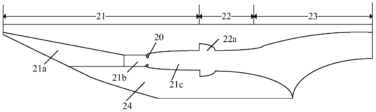
[0037] figure 2 It is a schematic diagram of a plane structure of a shock-induced combustion ramjet engine according to an embodiment of the present invention.

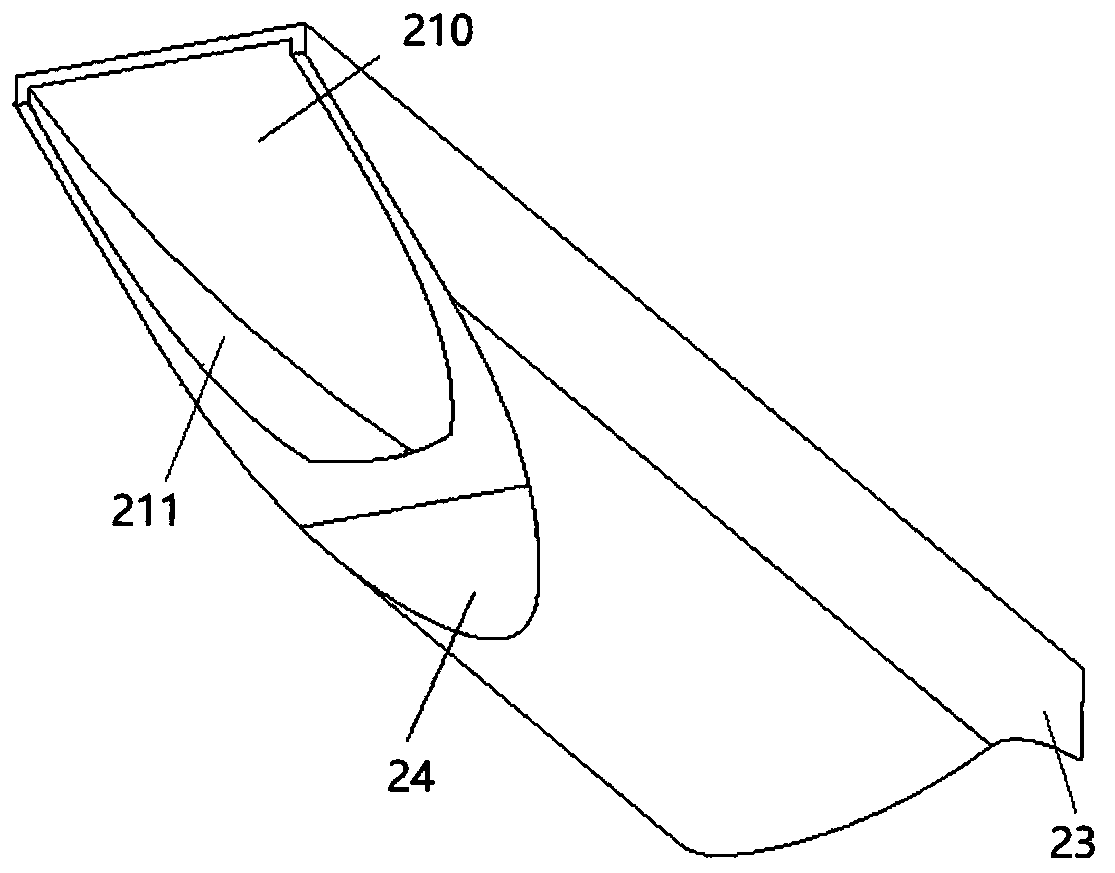
[0038] The shock-induced combustion ramjet engine includes: a fuel injector 20, a square-turn-circular internally retractable intake port 21, a combustion chamber 22, and a tail nozzle 23. The square-turn inner-contracting intake port 21 includes a first intake port section 21a, a second intake port section 21b, and a mixing section 21c. The first intake port section 21a includes the inner cavity of the first intake port section 21a. The first wall surface 210 and the second wall surface 211, the first wall surface 210 is a flat surface, the second wall surface 211 is an arc surface, and the first air inlet section 21a gradually moves from the inlet to the second air inlet section 21b. When contracted, the second air inlet section 21b communicates with the first air inlet section 21a, which is cylindrical, and the mixin...

Embodiment 2

[0049] In this embodiment, the shock-induced ignition ram-launching method includes the following steps: setting the intake port as a square-turn-circle inward-contracting intake port to include a first intake port section and a second intake port section And the mixing section, the first intake port section includes a first wall surface and a second wall surface constituting the inner cavity of the first intake port section, the first wall surface is a flat surface, the second wall surface is an arc surface, and the first intake port section is From the inlet to the second inlet section, it gradually shrinks, the second inlet section is connected with the first inlet section, which is cylindrical, and the mixing section is connected with the second inlet section; The fuel injector is set at the entrance of the mixing section; when the hypersonic flow enters the mixing section, the fuel injector injects fuel; the hypersonic flow is compressed in the first and second intake port ...


PUM


Abstract

The invention discloses a shock wave induced combustion ramjet engine and a shock wave induced combustion ramjet method. The ramjet engine comprises a square-to-round internal contraction type air inlet duct, a fuel injector, a combustion chamber and an exhaust nozzle. The square-to-round internal contraction type air inlet duct comprises a first air inlet duct section, a second air inlet duct section and a mixing section. The first air inlet duct section comprises a first wall surface and a second wall surface. The first wall surface is a plane surface and the second wall surface is an arc surface. The first air inlet duct section gradually contracts from an inlet to the second air inlet duct section. The second air inlet duct section is cylindrical. The mixing section is communicated with the second air inlet duct section. The fuel injector is located at the inlet position of the mixing section, the combustion chamber is communicated with the mixing section, and the combustion chamber is not provided with the fuel injector. The shock wave induced combustion ramjet engine uses detonation to organize combustion, the combustion distance is shorter, and the fuel and gas are mixed andcombusted more fully, so that the length of the combustion chamber can be designed to be shorter, and the propulsion performance of the ramjet engine can be greatly improved.

Description

Technical field [0001] The present invention relates to the technical field of air-breathing hypersonic propulsion, and more specifically, to a shock wave induced ramjet engine and a shock wave induced ramjet starting method. Background technique [0002] Hypersonic propulsion technology is the core key technology for the development of hypersonic aircraft. The scramjet is the best power device to achieve hypersonic flight. figure 1 It is a schematic diagram of the current conventional scramjet structure. The scramjet includes an intake port 11, a combustion chamber 12, and a tail nozzle 13. The combustion chamber 12 has a fuel injector 12a for injecting fuel. The working principle of the conventional scramjet is that the high-speed flow enters the intake port 11 and is compressed by the slope surface of the upper wall to generate shock waves. The compressed shock wave enters the combustion chamber 12, and the fuel injector 12a provided at the front of the combustion chamber 1...

Claims


Application Information

Patent Timeline
Patent Type & Authority Patents(China)
IPC IPC(8): F02K7/14F02C7/042
CPCF02C7/042F02K7/14
Inventor 滕宏辉郗雪辰
Owner BEIJING INSTITUTE OF TECHNOLOGYGY
Why Eureka
Try Eureka