Supercharge Your Innovation With Domain-Expert AI Agents!

Three-swirl-flow low-CO and high-efficiency pulverized coal burner

A pulverized coal burner and high-efficiency technology, which are applied to burners, burners for burning powder fuel, combustion methods, etc., can solve the problems of incomplete combustion of carbon, increase of carbon monoxide content, and reduction of secondary air entrained pulverized coal momentum. , to achieve the effect of promoting pulverized coal combustion, efficient combustion, and enhanced swirl flow

Pending Publication Date: 2018-12-18
TRANSTEK IND HK LTD KOWLOON
View PDF1 Cites 0 Cited by
  • Summary
  • Abstract
  • Description
  • Claims
  • Application Information

AI Technical Summary

Problems solved by technology

[0004] However, while the dual-air swirl burner uses staged combustion to reduce NOx (nitrogen oxides) emissions, it reduces the secondary air of the main burner and reduces the momentum of the secondary air to entrain pulverized coal. Oxygen deficiency prevents the relatively thick coal powder from being in full contact with oxygen, resulting in incomplete combustion of carbon in the coal powder and a significant increase in the content of carbon monoxide (CO) in the flue gas, which will increase the heat loss of the boiler chemical incomplete combustion , thereby reducing the combustion efficiency of the boiler

Method used


Image

  • Three-swirl-flow low-CO and high-efficiency pulverized coal burner
  • Three-swirl-flow low-CO and high-efficiency pulverized coal burner

Examples


Embodiment Construction

[0022] The specific embodiment of the present invention and working process will be further described below in conjunction with accompanying drawing.

[0023] The orientation terms such as up, down, left, right, front and rear in this application document are established based on the positional relationship shown in the drawings. If the drawings are different, the corresponding positional relationship may also change accordingly, so this should not be understood as limiting the scope of protection.

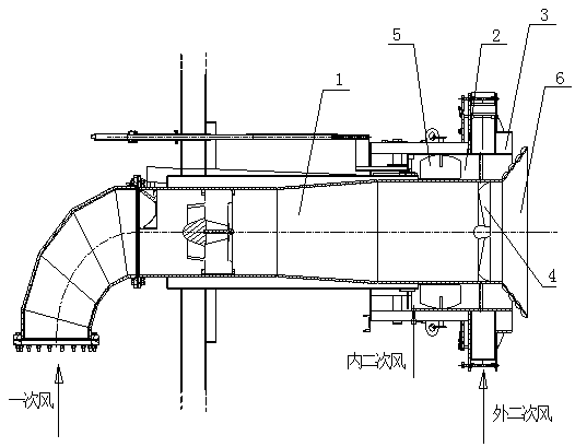
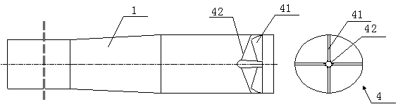
[0024] Such as figure 1 As shown, a three-swirl low-CO high-efficiency pulverized coal burner includes a primary air pulverized coal pipeline 1 , an inner secondary air pipeline 2 and an outer secondary air pipeline 3 arranged concentrically from the inside to the outside. A guide device 4 is arranged inside the outlet end of the primary air pulverized coal pipeline 1, and the guide device 4 is arranged at a distance of 50-150 mm from the outlet of the primary air pulverized coal...


PUM


Abstract

The invention relates to a three-swirl-flow low-CO and high-efficiency pulverized coal burner. The three-swirl-flow low-CO and high-efficiency pulverized coal burner comprises a primary air pulverizedcoal pipeline, an inner secondary air pipeline and an outer secondary air pipeline, wherein the primary air pulverized coal pipeline, the inner secondary air pipeline and the outer secondary air pipeline are concentrically arranged from inside to outside in sequence. A guiding device is arranged at the position of 50-150mm on the inner side the outlet end of the primary air pulverized coal pipeline, and a swirl increasing device is arranged at the outlet end. The guiding device comprises a bluff body and a plurality of vanes uniformly fixed to the bluff body along the circumference in a distributed mode. The vanes select and use airfoil vanes and fixed to the blunt body by 10-30 degrees, and the surfaces of the vanes are sprayed with high temperature abrasion-proof material. Guiding vanesare arranged on the middle portion of the inner secondary air pipeline, and the guiding vanes select and use shutter type swirl vanes. The swirl increasing device is arranged in a gradually expandingring structure, a plurality of weak disturbance end blocks are arranged along the circumference of the inner side of the gradually expanding ring structure, and a plurality of strong disturbance endblocks are arranged along the circumference of the outer side of the gradually expanding ring structure. The widths and heights of the windward end faces of the weak disturbance end blocks are smallerthan the widths and heights of the windward end faces of the strong disturbance end blocks. The three-swirl-flow low-CO and high-efficiency pulverized coal burner has the advantages of sufficient mixing of pulverized coal and air, and complete burning and high efficiency.

Description

technical field [0001] The invention relates to a three-swirl low-CO high-efficiency pulverized coal burner, which belongs to the technical field of combustion. Background technique [0002] For pulverized coal boilers burning bituminous coal, once-through burners arranged in corners and swirl burners arranged in walls are generally used. At present, the wall-mounted burner mainly adopts a double-air swirl burner to solve the problem of ignition and stable combustion of pulverized coal. Due to the increasingly stringent national environmental protection requirements, wall-mounted swirl burners need to set OFA (overfired air) to control NOx (nitrogen oxides) emissions at the boiler outlet. [0003] The double-adjustable air swirl burner is mainly composed of primary air pulverized coal pipes, inner and outer secondary air ducts. The primary air passing through the pulverizing system carries the pulverized coal from the primary air pipe of the burner into the furnace in a st...

Claims


Application Information

Patent Timeline
Patent Type & Authority Applications(China)
IPC IPC(8): F23D1/02
CPCF23D1/02Y02E20/34
Inventor 韩振杰韩冰
Owner TRANSTEK IND HK LTD KOWLOON
Features
  • R&D
  • Intellectual Property
  • Life Sciences
  • Materials
  • Tech Scout
  • Unparalleled Data Quality
  • Higher Quality Content
  • 60% Fewer Hallucinations
Learn More