
A system for detecting and diagnosing lung neoplasms on CT images

A CT image and lung technology, applied in the field of image processing, can solve the problems of nodule classification limitation, inaccurate segmentation, loss of nodule information, etc., and achieve the effect of improving automation, reducing workload and high sensitivity

Inactive Publication Date: 2018-12-18
HARBIN UNIV OF SCI & TECH
View PDF2 Cites 9 Cited by
  • Summary
  • Abstract
  • Description
  • Claims
  • Application Information

AI Technical Summary

Problems solved by technology

Threshold method and region growth algorithm are commonly used for lung segmentation. Such methods may mis-segment near-pleural nodules in the segmentation results, resulting in the loss of nodule and other lesion information, or the segmentation is not accurate enough to meet the needs of clinical diagnosis; segmentation After the lung parenchyma area is obtained, candidate nodules are detected in the lung parenchyma area. Whether it is a detection method based on gray threshold, a detection method that combines shape features and gray features, or a detection method based on filtering, it will make the detection The results contain a large number of false positive results, so after the candidate nodules are detected, the candidate nodules need to be classified to eliminate false positive candidates; in order to eliminate false positive candidates and diagnose nodules, most of them use rule-based classification method or linear classification method, however, these two types of classification methods have limitations in classifying nodules and non-nodules, among which rule-based classifiers can only distinguish nodules with special shapes, since the features extracted from candidate nodules are mostly nonlinear , so the linear classifier cannot get satisfactory results

Method used


Image

  • A system for detecting and diagnosing lung neoplasms on CT images
  • A system for detecting and diagnosing lung neoplasms on CT images
  • A system for detecting and diagnosing lung neoplasms on CT images

Examples


Embodiment Construction

[0038] Embodiments of the present invention will be described in detail below in conjunction with the accompanying drawings.

[0039] It should be clear that the described embodiments are only some of the embodiments of the present invention, not all of them. Based on the embodiments of the present invention, all other embodiments obtained by persons of ordinary skill in the art without creative efforts fall within the protection scope of the present invention.

[0040] Specific examples of the present invention are provided below to help understanding of the present invention.

[0041] Such as figure 1 As shown, the lung tumor detection and diagnosis system based on CT images provided by the present invention includes:

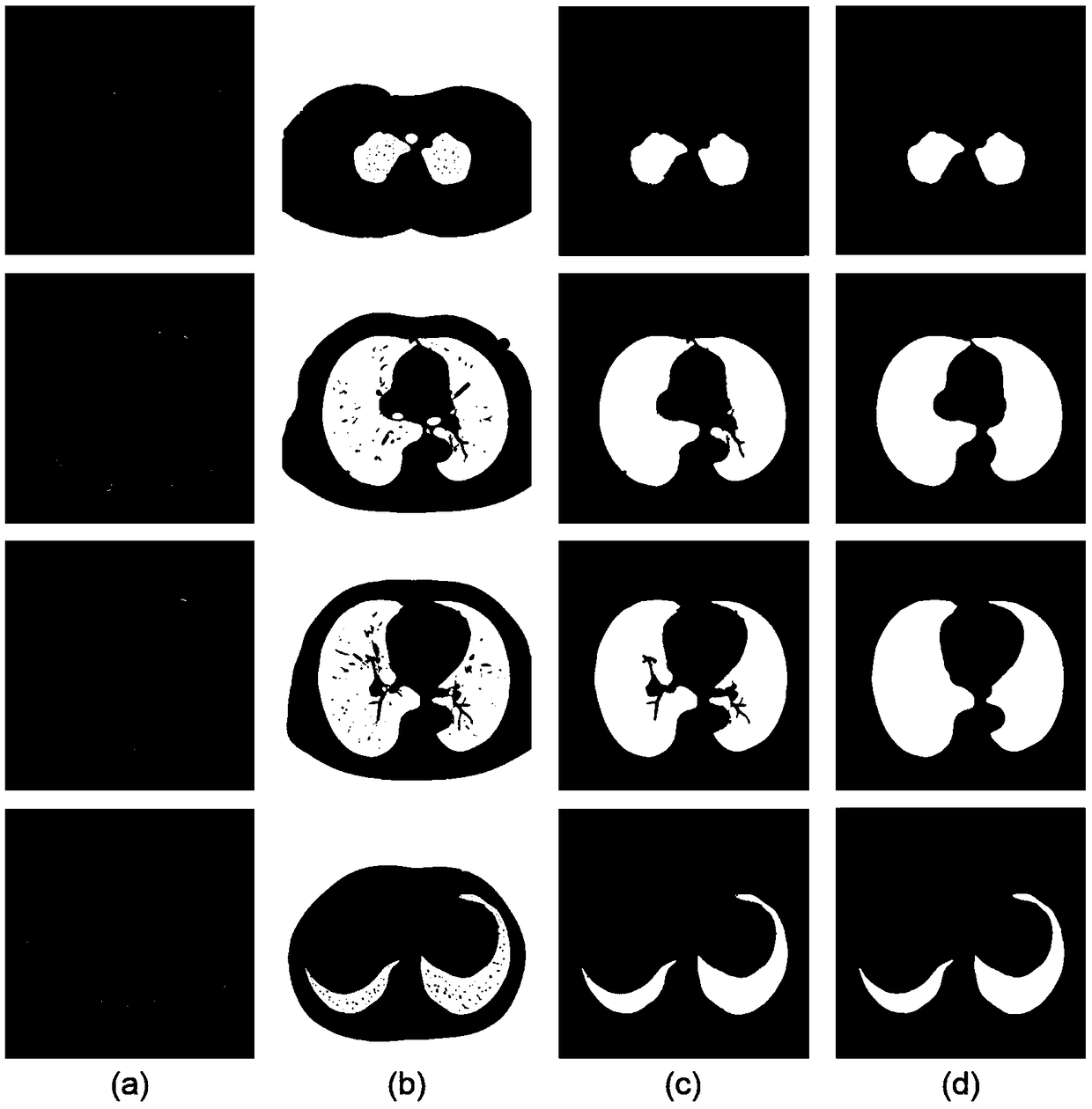
[0042] a) lung parenchyma segmentation module, which processes the obtained chest CT image, and separates the lung parenchyma area from the chest area and irrelevant areas outside the body;

[0043] b) The candidate nodule detection module detects the segm...


PUM


Abstract

A system for detecting and diagnosing lung neoplasms on CT images is provided. The system consists of a lung parenchyma segmentation module, a candidate nodule detection module and a candidate nodulediagnosis module. In the lung segmentation module, the original CT image is morphologically denoised, then the binary segmentation is performed by the optimal threshold method, the initial boundary isextracted by the boundary tracking method, the boundary is repaired by the boundary matching repair algorithm, and finally the lung parenchyma is segmented by the flood filling algorithm. In the candidate nodule detection module, the candidate nodule detection algorithm based on ring filter and the candidate nodule detection algorithm based on threshold are combined. The detection results will include a large number of false positives. First, the rule method is used to eliminate the false positives, and then the fuzzy super-box neural network based on K-means clustering algorithm is used as asystem classifier for the diagnosis of candidate nodules. This system provides a good support for doctors to diagnose lung cancer.

Description

technical field [0001] The invention relates to the technical field of image processing, in particular to a system for detecting and diagnosing lung tumors based on CT images. Background technique [0002] At present, CT images have become the most common method for detecting lung cancer. With the improvement of CT accuracy, the number of CT images generated by each scan has also increased greatly, and the diagnostic workload of radiologists has increased, which is likely to cause misdiagnosis. The use of computer-aided diagnosis system CAD can Provide effective assistance to doctors, reduce the workload of medical staff, and improve the efficiency and accuracy of diagnosis. [0003] The pulmonary nodule auxiliary diagnosis system generally needs to go through three steps: lung region segmentation, candidate nodule detection, and candidate nodule classification diagnosis. Threshold method and region growth algorithm are commonly used for lung segmentation. Such methods may ...

Claims


Application Information

Patent Timeline
IPC IPC(8): G06T7/00G06T7/11G06T7/136
CPCG06T7/0012G06T7/11G06T7/136G06T2207/10081G06T2207/30064G06T2207/30096
Inventor 王进科晏清微祖宏亮孙艳霞毕蓉蓉
Owner HARBIN UNIV OF SCI & TECH
Learn More