Tightly coupled antenna array with wide bandwidth, wide angle and low profile

A low-profile, tight-coupling technology, applied in the field of radar and communications, can solve the problems of antenna feed structure integration, antenna element coupling and difficult precise modulation, and achieve good stability, wide bandwidth angle characteristics, and compact and simple structure.

Active Publication Date: 2018-12-18
FUDAN UNIV
View PDF19 Cites 10 Cited by
  • Summary
  • Abstract
  • Description
  • Claims
  • Application Information

AI Technical Summary

Problems solved by technology

However, the traditional current sheet is only a rational model, and various problems will be encountered in engineering problems, such as the coupling between antenna elements is difficult to precisely modulate, the integration of the antenna feed structure, and due to Scanning blind angle introduced by surface wave and common mode resonance, etc.

Method used


Image

  • Tightly coupled antenna array with wide bandwidth, wide angle and low profile
  • Tightly coupled antenna array with wide bandwidth, wide angle and low profile
  • Tightly coupled antenna array with wide bandwidth, wide angle and low profile

Examples


Embodiment Construction

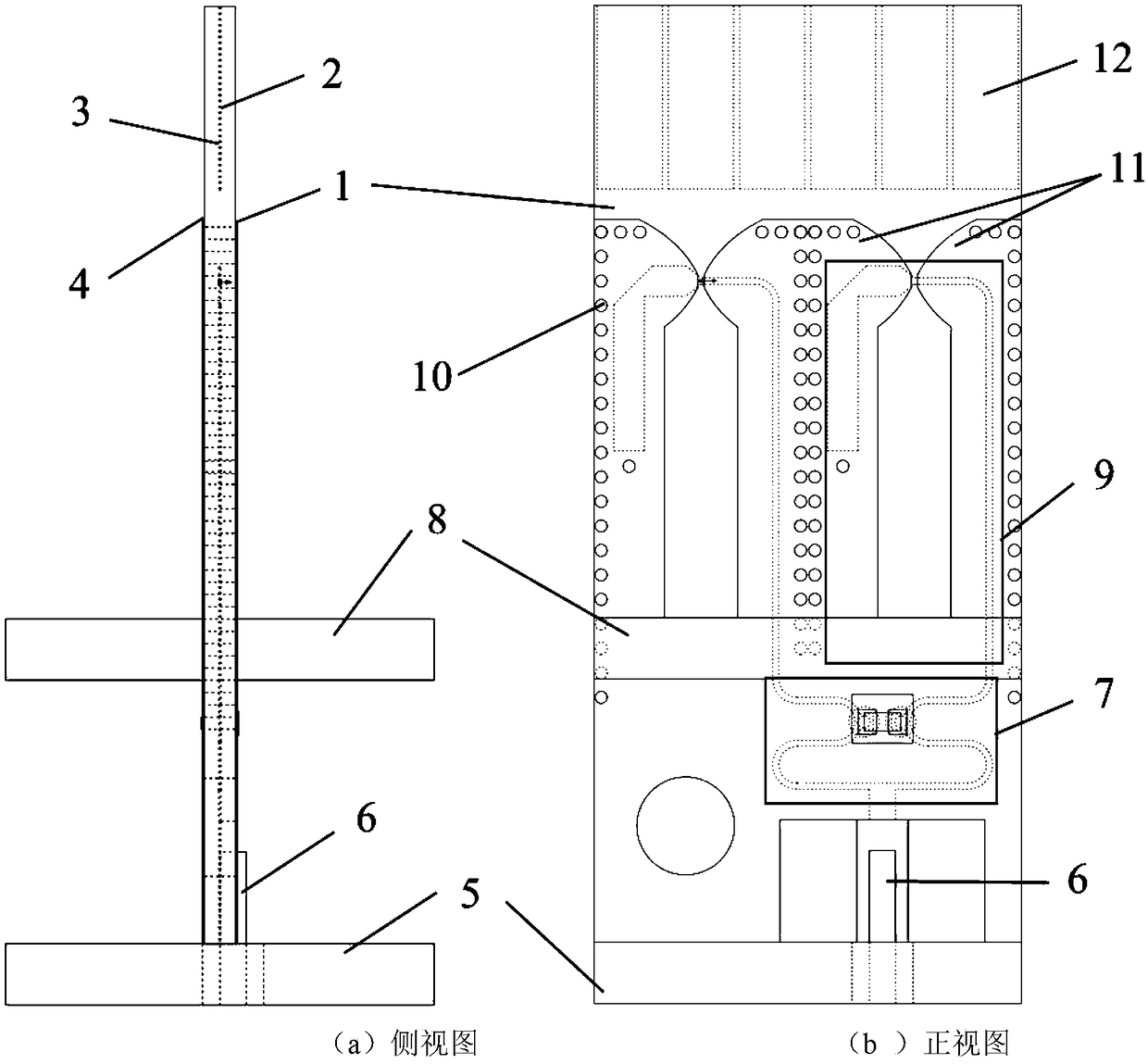
[0029] Such as figure 1 The schematic diagram of the unit of the tightly coupled antenna array is shown. The antenna is mainly composed of two parts, namely the antenna line and the support, which are processed separately. The antenna line is processed by the traditional PCB process, while the support is machined by the CNC machine tool.

[0030] The antenna circuit has a four-layer structure, that is, the circuit structure layer 1 on the upper surface of the upper dielectric board, the circuit structure layer 2 on the lower surface of the upper dielectric board, the circuit structure layer 3 on the upper surface of the lower dielectric board, and the circuit structure layer on the lower surface of the lower dielectric board 4. It is made of two dielectric copper-clad laminates. Before lamination, the required lines are etched on the upper dielectric board and the lower dielectric board by traditional photolithography process, and then drilled with a drilling machine after lami...


PUM


Abstract

The invention belongs to the field of radar technology and communication technology, in particular to a tightly coupled antenna array with wide bandwidth, wide angle and low profile. The antenna arraycomprises a supporting member composed of a supporting plate, a supporting plate frame, a reflecting plate and a feeding joint, and an antenna line composed of a Wilkinson power divider, a feeding balun, a radiation current sheet and a frequency selection surface; The antenna line is laminated by two dielectric copper clad plates, and are divided into four layers: circuit structure layers of theupper and lower layers of an upper layer dielectric plate and circuit structure layers of the upper and lower layers of a lower layer dielectric plate; the first and fourth layers are in a symmetricalradiation structure, the second layer is an empty plate, and the third layer is provided with the power divider and balun. The first and fourth layers are electrically connected through conductive vias to provide a closed environment for the third layer and suppress energy leakage. The radiation current sheet is symmetrically distributed, which can reduce the impedance at the point where the balun is coupled with the current sheet. Frequency selective surface is located on the third layer, which can be used to replace the impedance matching dielectric layer on the current sheet, so that the antenna can be fabricated and installed more easily.

Description

technical field [0001] The invention belongs to the technical field of radar and communication, and in particular relates to a tightly coupled antenna array. Background technique [0002] In today's electronic systems, it is often necessary to install multiple antennas of different forms to achieve different functions. For example, in the military field, there are search radar, fire control radar, communication radar and identification friend or foe radar, etc.; while in the civilian communication field, there are 2G communication Antenna, 3G communication antenna and 4G communication antenna, etc. Usually, these radars or antennas need to be installed on a platform due to various factors. However, due to problems such as electromagnetic interference and space size restrictions, the performance of each antenna is seriously affected; and in the process of installation and debugging, it takes a lot of time to minimize the interference between antennas, which greatly increases...

Claims


Application Information

Patent Timeline
Patent Type & Authority Applications(China)
IPC IPC(8): H01Q1/12H01Q21/06H01Q15/00
CPCH01Q1/12H01Q15/0013H01Q21/061
Inventor 尹卫爽关放梁修业张喆刘晓晗资剑
Owner FUDAN UNIV
Why Eureka
Try Eureka