Device and method for lightning damage monitoring of sandwich components based on built-in fiber grating
A fiber Bragg grating and damage monitoring technology, applied in measurement devices, optical devices, heat measurement, etc., can solve problems such as difficulty in detecting internal damage of materials, large sensor size, and inability to obtain monitoring data.
- Summary
- Abstract
- Description
- Claims
- Application Information
AI Technical Summary
Problems solved by technology
Method used
Image
Examples
Embodiment 1
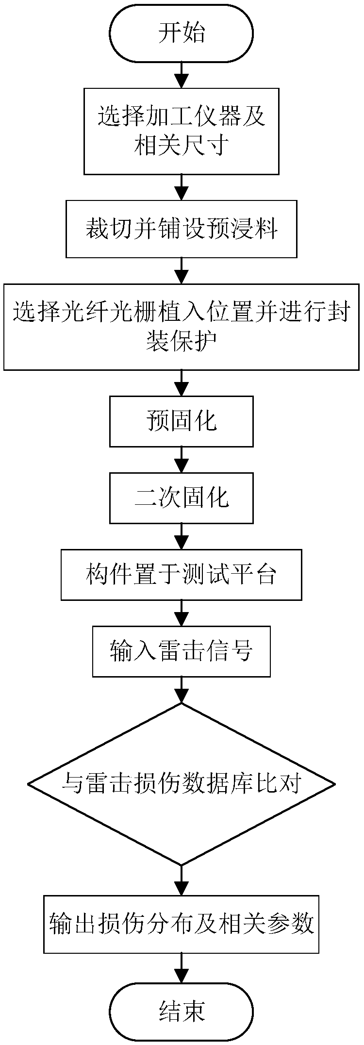
[0075] One kind of 300mm×300mm, the ply sequence is [-45 2 / 0 2 / 45 2 / 90 2 / 0 / 90 / 0]sFiber composite sandwich components (eg figure 1 ) Lightning strike damage online monitoring device and preparation method thereof. In this embodiment, a fiber Bragg grating is selected.
[0076] [-45 2 / 0 2 / 45 2 / 90 2 / 0 / 90 / 0]s means: first lay two layers of prepreg at -45°, then two layers of prepreg at 0°, then two layers at 45°, two layers at 90°, one layer at 0°, and one layer at 90° , 0° one layer. This is half of a panel, with a total of 11 layers. The lowercase letter s means mirror symmetry. Lay it again in the reverse order of the layering sequence just now, totaling 22 layers.
[0077] The equipment used includes: carbon fiber / epoxy resin prepreg, aramid honeycomb, fiber Bragg grating, thermal molding press, fiber grating demodulator.
[0078] 1. Implantation position of fiber grating sensor
[0079] (1) The positions and coordinates of the sensors on the upper panel ar...
Embodiment 2
[0090] One kind of 300mm×300mm, the ply sequence is [-45 2 / 0 2 / 45 2 / 90 2 / 0 / 90 / 0]s fiber composite sandwich components (eg figure 1 ) Lightning strike damage online monitoring device and preparation method thereof. In this embodiment, a fiber Bragg grating is selected.
[0091] The equipment used includes: carbon fiber / epoxy resin prepreg, aramid honeycomb, fiber Bragg grating, autoclave, fiber grating demodulator.
[0092] 1. Implantation position of fiber grating sensor
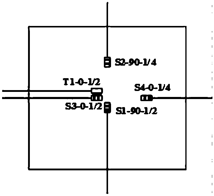
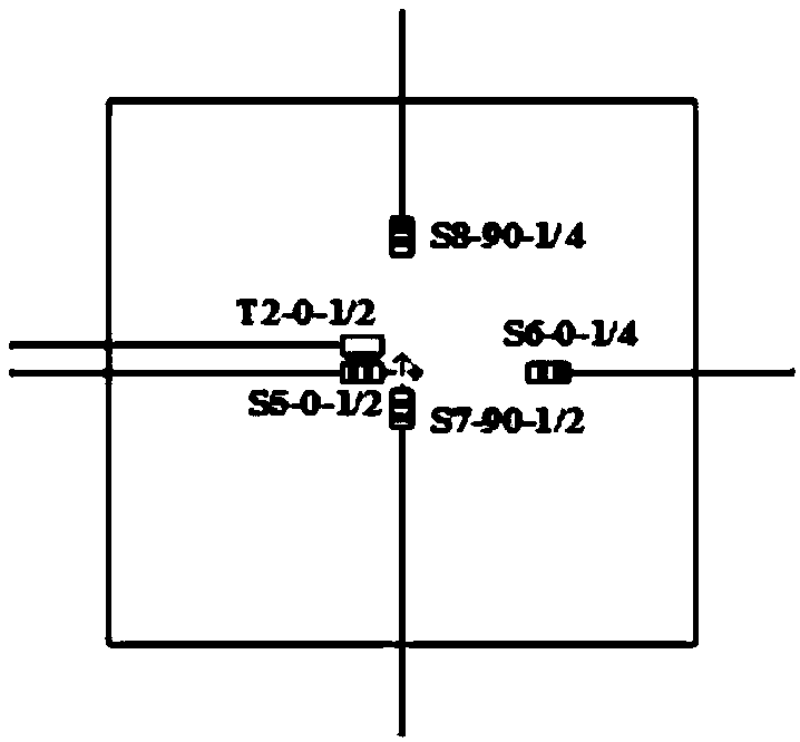
[0093] (1) The positions and coordinates of the sensors on the upper panel are respectively: S1-90-1 / 2 and S2-90-1 / 4 are respectively implanted in 1 / 1 of the 90° centerline between the 15 and 16 layers of prepreg 2 and 1 / 4, the coordinates are (0, -15), (0, 75) respectively. S3-0-1 / 2 and S4-0-1 / 4 are respectively implanted at 1 / 2 and 1 / 4 of the 0° centerline between 11 and 12 layers of prepreg, and the coordinates are (-15, 0 ), (75, 0) (as shown in Figure 2(a) and Figure 2(b)).
[0094] In orde...
PUM
| Property | Measurement | Unit |
|---|---|---|
| thickness | aaaaa | aaaaa |
| compressive strength | aaaaa | aaaaa |
| compressive strength | aaaaa | aaaaa |
Abstract
Description
Claims
Application Information
 - R&D
- Intellectual Property
- Life Sciences
- Materials
- Tech Scout
- Unparalleled Data Quality
- Higher Quality Content
- 60% Fewer Hallucinations
Browse by: Latest US Patents, China's latest patents, Technical Efficacy Thesaurus, Application Domain, Technology Topic, Popular Technical Reports.
© 2025 PatSnap. All rights reserved.Legal|Privacy policy|Modern Slavery Act Transparency Statement|Sitemap|About US| Contact US: help@patsnap.com


