
Adjustable small-wavelength interval optical transceiver

A wavelength interval, optical transceiver technology, applied in the direction of light guides, optics, instruments, etc., can solve problems such as abnormal operation of the receiving end, inability to shield optical signals, and difficulties in operation and maintenance, so as to achieve convenient operation and maintenance and prevent received optical signals from entering into the Optical transmitter, to achieve the effect of the handshake mechanism

Active Publication Date: 2018-12-21
珠海奇芯光电科技有限公司
View PDF6 Cites 4 Cited by
  • Summary
  • Abstract
  • Description
  • Claims
  • Application Information

AI Technical Summary

Problems solved by technology

The dual-fiber optical transceiver needs two optical fibers, one optical fiber for uplink transmission and one optical fiber for downlink transmission. Only one optical fiber is used, but because of different wavelengths, two different optical modules are required, which brings difficulties to operation and maintenance. The receiving end of the existing single-fiber bidirectional optical transceiver uses filters for light splitting, which cannot shield The optical signal at the transmitting end, so the transmitting light has serious signal interference to the receiving end, and when the network is deployed, the reflection of any node on the optical fiber will cause the transmitting optical signal to return to the device, causing the receiving end to work abnormally

Method used


Image

  • Adjustable small-wavelength interval optical transceiver
  • Adjustable small-wavelength interval optical transceiver
  • Adjustable small-wavelength interval optical transceiver

Examples


Embodiment Construction

[0027] The following will clearly and completely describe the technical solutions in the embodiments of the present invention with reference to the drawings in the embodiments of the present invention.

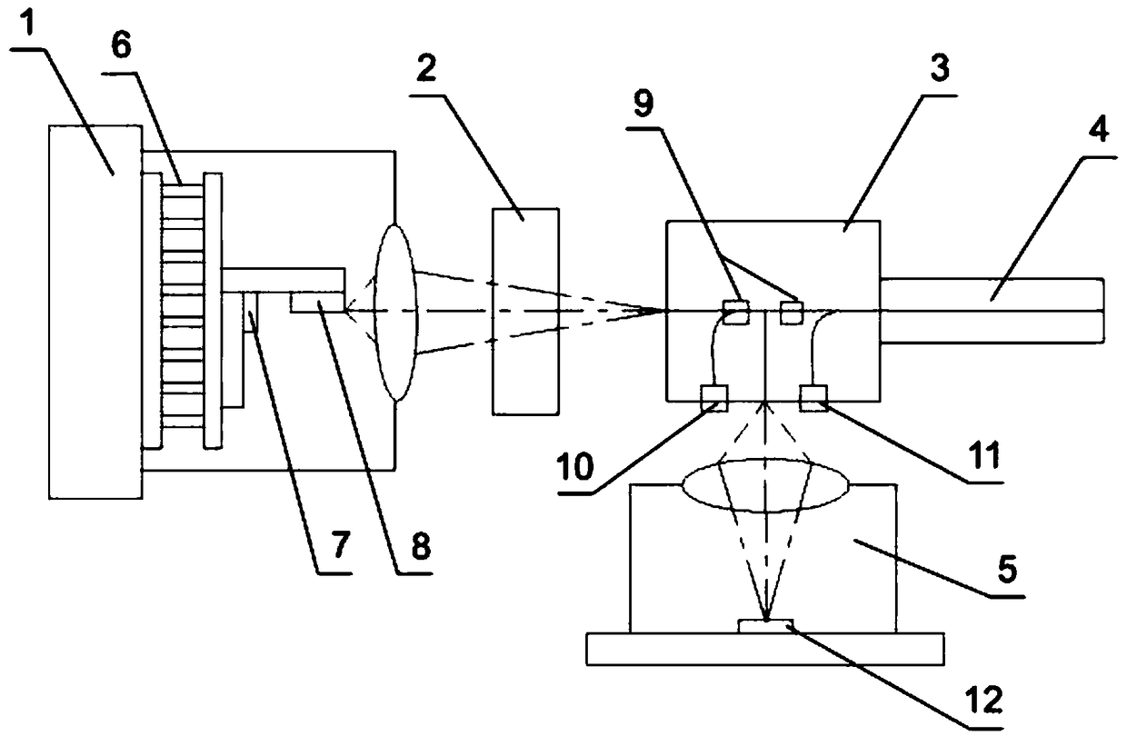
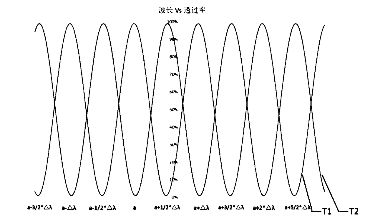
[0028] The present invention provides an adjustable small wavelength interval optical transceiver, whose working principle is to replace the traditional spatial optical comb filter with a comb filter based on PLC, and change the wavelength of the laser by changing the temperature inside the laser transmitter , so that it can be used in conjunction with the comb filter to complete dual multiplexing, so that the light at the transmitting end can pass through the filter and enter the single-mode fiber, and prevent the received optical signal from entering the optical transmitting end, while preventing the optical signal at the local transmitting end from directly Enter the local receiving end to cause optical crosstalk problems.

[0029] The present invention will be described in...


PUM


Abstract

The invention discloses an adjustable small-wavelength interval optical transceiver, which comprises a laser emitter, an isolator, a comb filter, a single-mode optical fiber adapter and a laser receiver, wherein the laser emitter, the isolator, the comb filter and the single-mode optical fiber adapter are arranged on the same level; the isolator is arranged between the laser emitter and the comb filter; the single-mode optical fiber adapter is installed on one end, which is far away from the laser emitter, of the comb filter; and the laser receiver is arranged on the side of the comb filter. The PLC (Programmable Logic Controller) comb filter is used for replacing a traditional space light comb filter, temperature in the laser emitter is changed so as to change the wavelength of the laser,so that the laser emitter is cooperated with the comb filter to finish double-channel multiplexing, the light of a transmitting terminal successfully passes through the filter to enter the single-mode optical fiber, a received optical signal is prevented from entering the light transmitting terminal, meanwhile, a situation that the optical signal of the local transmitting terminal directly entersa local receiving terminal to cause a light crosstalk problem is avoided, and a purpose of simplifying a technology and lowering cost is realized.

Description

technical field [0001] The invention relates to the technical field of single-fiber bidirectional optical transceivers, in particular to an adjustable small wavelength interval optical transceiver. Background technique [0002] In recent years, as the deployment of 4G and 5G networks has deepened, the number of base stations has increased and the sites have become denser. The deep coverage of base stations requires deployment closer to users. Therefore, centralized deployment of BBUs and RRUs, and heterogeneous groups of base stations Internet and other technologies have become the development trend of mobile networks. At present, point-to-point fiber optic direct connection is the main mode of mobile fronthaul. There are a series of problems such as serious fiber resource consumption, difficult expansion, high construction and operation costs, and error-prone installation. How to solve these problems has become the focus of attention. [0003] Optical transceivers used in ...

Claims


Application Information

Patent Timeline
Patent Type & Authority Applications(China)
IPC IPC(8): G02B6/42
CPCG02B6/4209G02B6/4215G02B6/4246
Inventor 冯亮王强徐之光马云振
Owner 珠海奇芯光电科技有限公司
Learn More