
Optimized laser projection virtual keyboard

A virtual keyboard and laser projection technology, which is applied in the field of electronic information, can solve the problems of inconvenient carrying, poor anti-interference performance, and poor anti-interference performance of the laser projection virtual keyboard, and achieve the elimination of interference from large objects, good stability, and easy portability. Effect

Pending Publication Date: 2018-12-21
ZHENGZHOU UNIV
View PDF0 Cites 2 Cited by
  • Summary
  • Abstract
  • Description
  • Claims
  • Application Information

AI Technical Summary

Problems solved by technology

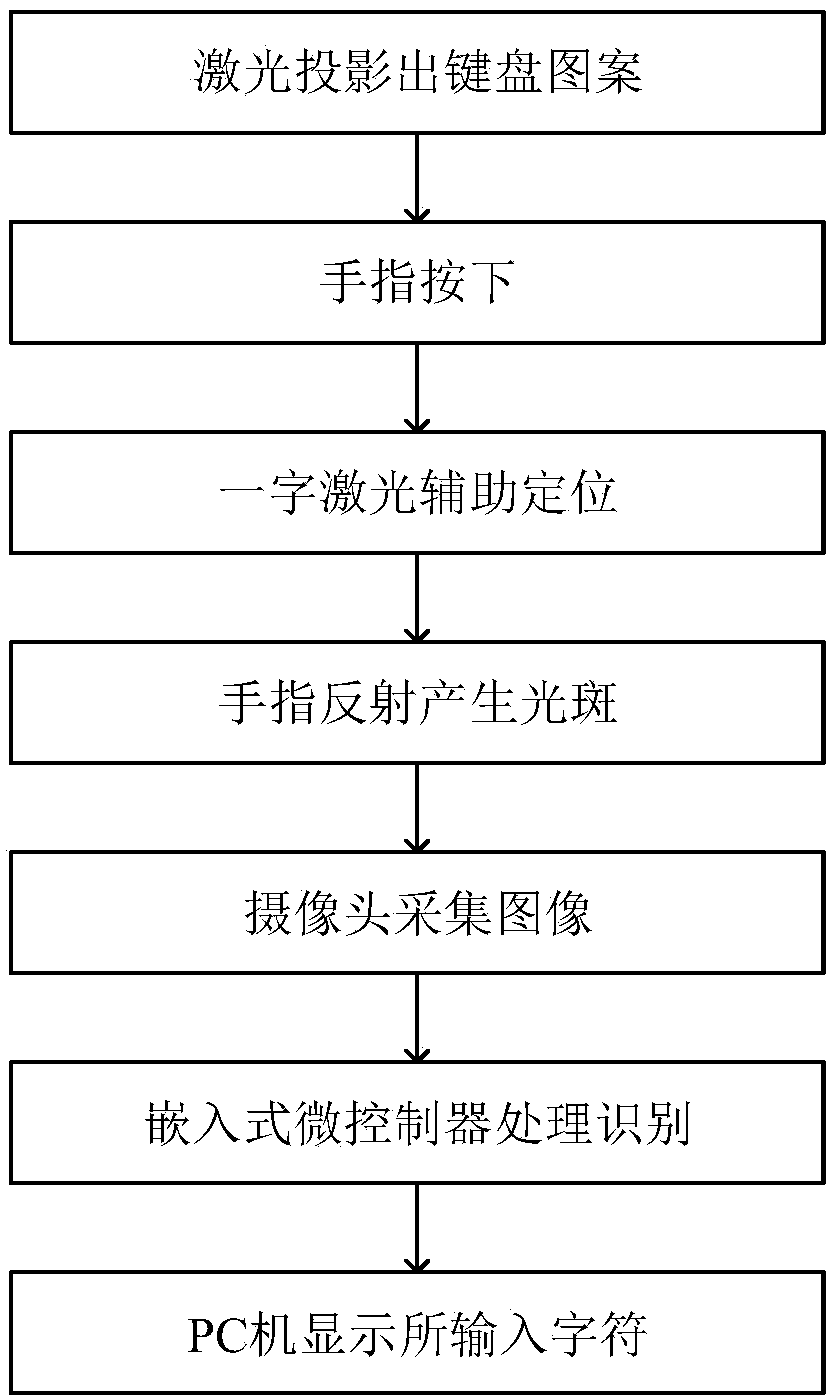
[0006] Aiming at the problems of inconvenient portability, inconvenient use, and poor anti-interference performance of the existing laser projection virtual keyboard, the present invention proposes a simple structure, low price, small size, easy to carry, easy to use, good stability, and can complete An optimized laser projection virtual keyboard that replaces the traditional physical keyboard, using visible red laser light to project the keyboard pattern; using a word laser to assist positioning; using a camera to collect image information; the collected image is processed by an embedded microcontroller Processing and identification, it can be used directly by connecting to the computer via USB; the communication between the virtual keyboard and the PC is carried out by using the USB communication module, and the algorithm of eliminating large object interference is adopted, which can effectively eliminate the interference of large objects inside the keyboard area and realize the palm Or the arm can be placed on the laser projection virtual keyboard, and there will be no false touch phenomenon; the algorithm of eliminating external interference is adopted, and when there are other objects around the keyboard, it will not interfere with the normal input of the keyboard, which solves the problem of carrying the existing laser projection virtual keyboard. Inconvenient, inconvenient to use, poor anti-interference

Method used


Image

  • Optimized laser projection virtual keyboard
  • Optimized laser projection virtual keyboard
  • Optimized laser projection virtual keyboard

Examples


Embodiment Construction

[0035] The present invention is further described in conjunction with the following examples.

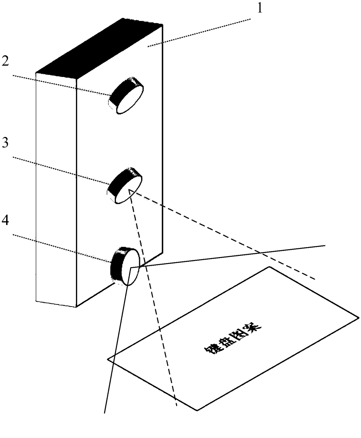
[0036] see figure 1 , the image acquisition module is an infrared camera 2, and the infrared camera 2 is fixed on the upper end of the upright metal casing 1 with the desktop at an angle of 30 degrees. The infrared camera 2 collects the image information of the keyboard area, and transmits it to the embedded microcontroller for Image processing and recognition.

[0037] see figure 1 , the keyboard projection laser 3 includes a visible red laser lamp with a power of 40mw and a grating lens containing a keyboard pattern, the keyboard projection laser 3 is fixed on the middle of the upright metal casing 1 at an angle of 53 degrees on the desktop, and the keyboard projection laser A virtual keyboard pattern is projected for assisting user input.

[0038] see figure 1, the one-word laser 4 is composed of a near-infrared light emitter with a power of 50mw and a one-word grating lens. ...


PUM


Abstract

The invention discloses an optimized laser projection virtual keyboard. The device comprises a carrier platform, an image acquisition module, a laser keyboard projection module, a laser positioning module, an image processing and identification module, a communication module and a power supply module. The carrier platform is an upright metal shell. The image acquisition module is a camera; the laser keyboard projection module comprises a visible red laser lamp and a grating lens containing a keyboard pattern; the laser positioning module comprises a near infrared light emitter and a word grating lens. The image processing and identification module is an embedded microcontroller. The communication module comprises a USB driver chip and a USB driver circuit. After optimization, the laser projection virtual keyboard processes and recognizes the image through embedded microcontroller, which can be used directly through USB connection computer, and the microcontroller has built-in interference elimination algorithm for large objects and external interference elimination algorithm.

Description

technical field [0001] The invention relates to the technical field of electronic information, in particular to an optimized laser projection virtual keyboard. Background technique [0002] With the development of technology, human-computer interaction is developing in a natural and non-invasive direction. Image processing and projection can be combined more flexibly, naturally and transparently. As an important input device for computers, the keyboard is unavoidable in the foreseeable future. What is missing is that the traditional physical keyboard is bulky and not easy to carry, which cannot meet the requirements of portability. Therefore, it is necessary to design and develop a laser projection virtual keyboard system that is small in size, easy to carry, easy to use, and strong in stability. [0003] The existing laser projection virtual keyboard has the following disadvantages: first, the self-made virtual keyboard is large in size and inconvenient to carry; second, th...

Claims


Application Information

Patent Timeline
Patent Type & Authority Applications(China)
IPC IPC(8): G06F3/02
CPCG06F3/0202G06F3/0219
Inventor 逯鹏韩坤峰朱西昆韩昕哲陈海洋赵乙霏王汉章刘超汪盈盈漆连鑫奚昊张亚彬高杨
Owner ZHENGZHOU UNIV
Learn More