
Apical-dominance sound barrier design method based on flow resistance and surface density coupling grading

A technology with top advantages and design methods, applied in the direction of sounding equipment, instruments, etc., can solve the problems of insignificant noise reduction and poor noise reduction effect, saving production and maintenance costs, wide application range, and improved noise reduction performance. Effect

Pending Publication Date: 2018-12-21
LOW SPEED AERODYNAMIC INST OF CHINESE AERODYNAMIC RES & DEV CENT
View PDF5 Cites 0 Cited by
  • Summary
  • Abstract
  • Description
  • Claims
  • Application Information

AI Technical Summary

Problems solved by technology

[0003] The current sound barrier has the problem of cutting-edge noise sources, so no matter what structure the sound barrier adopts, whether it is upright or deformed at the upper end, but because the overall design of the sound barrier uses the same material and structure, no matter how it is handled, its The noise reduction effect is very bad, only 3.6-6.5dB can be reduced
The actual noise source is simply replaced from one position to the tip of the sound barrier, and the noise reduction is of little significance

Method used


Image

  • Apical-dominance sound barrier design method based on flow resistance and surface density coupling grading
  • Apical-dominance sound barrier design method based on flow resistance and surface density coupling grading
  • Apical-dominance sound barrier design method based on flow resistance and surface density coupling grading

Examples


Embodiment 1

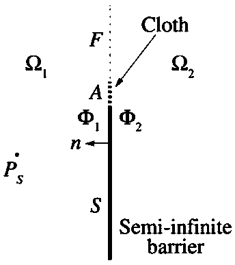
[0022] like figure 1 As shown in , a semi-infinite top dominant sound barrier model is established, which consists of two parts, the lower part S is the solid wall, the upper part A is the coupling gradient area of ​​flow resistance and surface density; F is the free space, and the left half Ω1 is the sound source Ps area, the right half Ω2 is the noise suppression area, Φ1 is the air particle velocity potential in the left half, and Φ2 is the air particle velocity potential in the right half.

[0023] In the design of the sound barrier, the structure of the S region and the A region can adopt any conventional structure, which can be a flat structure, a curved structure, or a bent plate with an inclination angle. However, no matter what structure is used, it is only necessary to ensure that the flow resistance and surface density of area A must gradually change from the top to the bottom. As long as this condition is met, the shape of the sound barrier can be designed arbitrar...


PUM


Abstract

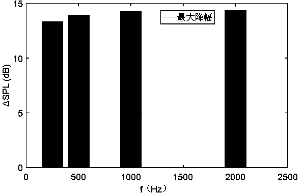
The invention discloses an apical-dominance sound barrier design method based on flow resistance and surface density coupling grading. The flow resistance and surface density coupling of the sound barrier from the top to bottom changes gradually; and the appearance of the sound barrier has a random surface structure on the premise of the flow resistance and surface density coupling grading the sound barrier from the top to bottom. According to the invention, On the basis of the sound barrier theory and calculation model, the apical-dominance sound barrier has the substantially improved noise reduction performance when being compared with the conventional sound barrier; and a reasonable surface density and flow resistance coupling design is provided for the noise frequency needing to be processed, so that the optimal noise reduction effect is realized; and compared with the traditional sound barrier, the apical-dominance sound barrier enables the target frequency noises to be reduced substantially, wherein the theoretical maximum noise reduction amplitude can reach 25dB. The provided apical-dominance sound barrier has advantages of simple structure and great convenience in maintenance; and the great noise reduction effect is realized without heightening.

Description

technical field [0001] The invention relates to the field of sound and noise processing, in particular to a method for designing a top-dominant sound barrier based on coupling gradients of flow resistance and surface density. Background technique [0002] With the development of railway construction and urban traffic, traffic noise pollution is becoming more and more serious, which needs to be solved urgently. As an effective method to reduce traffic noise pollution, sound barrier has been widely used at home and abroad. How to effectively use the noise barrier as a noise reduction measure to maximize its economic and technical effects is of great significance to improving the quality of residents' living environment. [0003] The current sound barrier has the problem of cutting-edge noise sources, so no matter what structure the sound barrier adopts, whether it is upright or deformed at the upper end, but because the overall design of the sound barrier uses the same materi...

Claims


Application Information

Patent Timeline
IPC IPC(8): G10K11/175
CPCG10K11/175
Inventor 郝南松陈鹏左孔成赵昱卢翔宇冉学军
Owner LOW SPEED AERODYNAMIC INST OF CHINESE AERODYNAMIC RES & DEV CENT
Learn More