Power system power flow calculation method andsystem and electronic device

A power system and power flow calculation technology, which is applied to circuit devices, AC network circuits, and AC networks with the same frequency from different sources, etc., can solve the problem of disconnection between state acquisition and power flow analysis, insufficient consideration of complex large power grids, and difficulty in meeting large power grids. Requirements for online real-time analysis of multi-scenario risk scenarios and other issues, to achieve strong data processing capabilities and computing capabilities, reduce management problems and communication overhead, and achieve real-time online power flow calculations

Inactive Publication Date: 2018-12-21
SHENZHEN INST OF ADVANCED TECH
View PDF5 Cites 9 Cited by
  • Summary
  • Abstract
  • Description
  • Claims
  • Application Information

AI Technical Summary

Problems solved by technology

[0008] (2) The power flow calculation is aimed at small areas, and insufficient consideration is given to complex large power grids: the current power flow algorithm is mainly realized by GPU computer through parallelization, mainly based on MPI and other technologies
In a large power grid, the amount of data will increase sharply. Only through local parallelization of a single machine, it is difficult to overcome defects such as insufficient memory and time-consuming IO reading and writing.
[0009] (3) The power topology changes frequently. The disconnection of network nodes and connections occurs frequently due to equipment failures and outages in the network. The power network topology is often in a dynamic process of change. The existing calculation methods are mainly used for long-term , Power flow calculation of relatively static network structure, real-time online calculation efficiency is low
[0010] (4) The scale and complexity of the network structure increases.

Method used


Image

  • Power system power flow calculation method andsystem and electronic device
  • Power system power flow calculation method andsystem and electronic device
  • Power system power flow calculation method andsystem and electronic device

Examples


Embodiment Construction

[0074] In order to make the purpose, technical solution and advantages of the present application clearer, the present application will be further described in detail below in conjunction with the accompanying drawings and embodiments. It should be understood that the specific embodiments described here are only used to explain the present application, not to limit the present application.

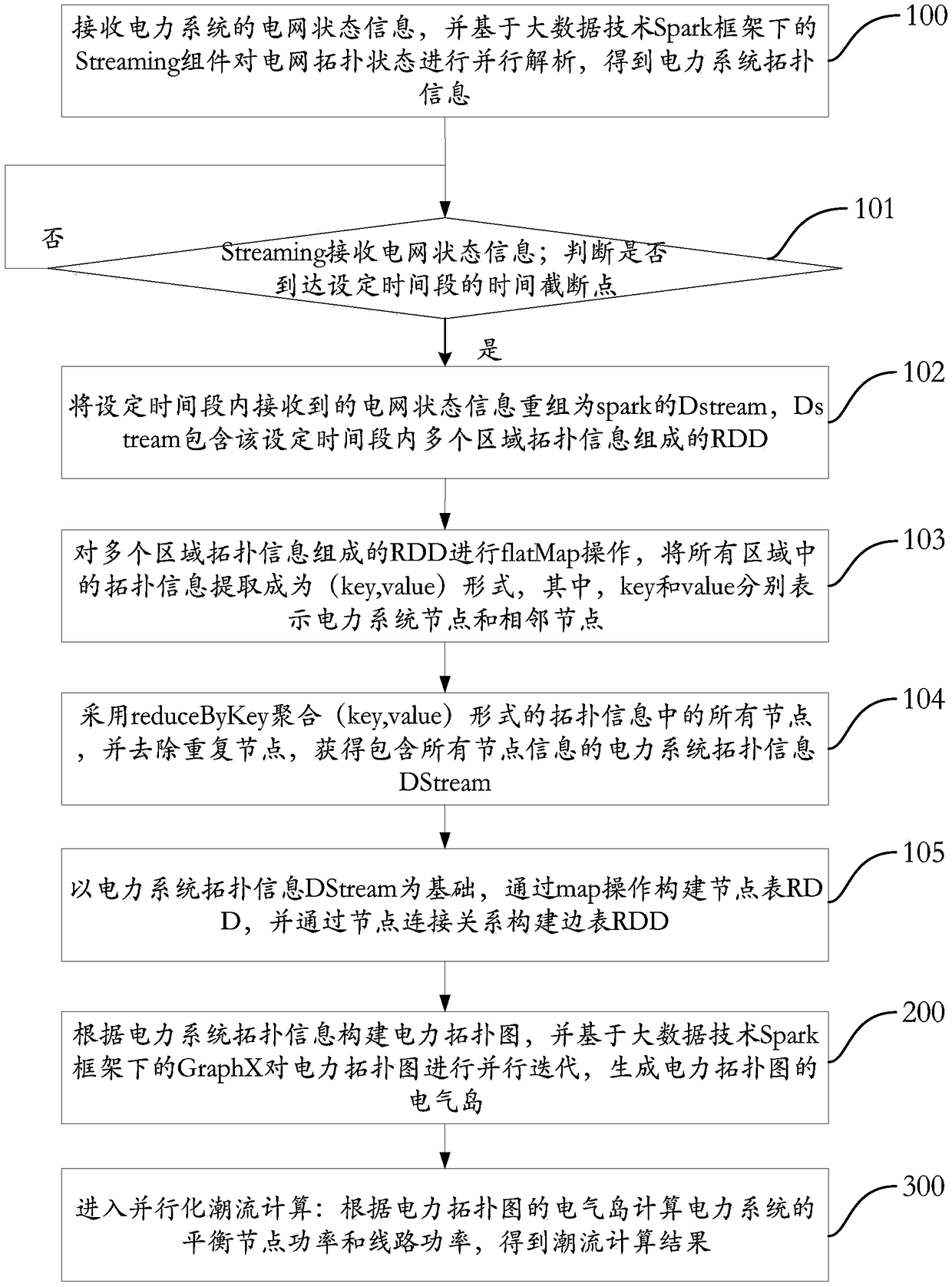
[0075] see figure 1 , is a flow chart of the power system power flow calculation method according to the embodiment of the present application. The power system power flow calculation method of the embodiment of the present application includes the following steps:

[0076] Step 100: Receive the grid status information of the power system, and analyze the grid topology status in parallel based on the Streaming component under the big data technology Spark framework to obtain the power system topology information;

[0077] In step 100, the grid state information supports two methods, the ...


PUM


Abstract

The present application relates to a power system power flow calculation method and system and an electronic device . The method comprises the following steps: a, analyzing the topology state of the power network in parallel based on the big data technology Spark to obtain the topology information of the power system; B, constructing a power topology diagram accord to the power system topology information, and carrying out parallel iteration on the power topology diagram based on the big data technology Spark to generate an electric island of the power topology diagram; c, calculating the balanced node power and the line power of the power system according to the electric island of the power topology diagram to obtain a power flow calculation result. The application supports the integratedanalysis of a power system in which a plurality of regions are interconnected, reduces the management problem and communication overhead caused by the centralized management of topology information,and has the characteristics of expandability, convenience for maintenance, and the like, and can effectively improve the utilization rate and computational efficiency of data, and realize the real-time online power flow calculation of large-scale complex power system.

Description

technical field [0001] The application belongs to the field of smart grid information technology, and in particular relates to a power system power flow calculation method, system and electronic equipment. Background technique [0002] Power flow calculation is a key part of power system risk assessment. Currently, power flow calculation has been widely used in power grid status assessment, risk assessment and other applications. Power system topology analysis is a prerequisite for power flow calculations, so power flow calculations must be performed on topological structures that have been constructed. However, with the increase of grid equipment, the number of nodes in the grid topology gradually increases, and the scale and complexity of the grid become increasingly complex. [0003] The rapid solution of large-scale power system power flow equations is the key basis for real-time and ultra-real-time stability analysis, reliability evaluation, and power flow tracking of ...

Claims


Application Information

Patent Timeline
IPC IPC(8): H02J3/06
CPCH02J3/06H02J2203/20
Inventor 何兵刘晟东胡金星郭媛君
Owner SHENZHEN INST OF ADVANCED TECH
Why Eureka
Try Eureka