An integrated field emission X-ray source
A field emission and X-ray technology, applied in the field of X-ray sources, can solve the problems of unstable emission current and low control precision, and achieve the effect of long-term working stability and life improvement, maintaining stability and high stability
- Summary
- Abstract
- Description
- Claims
- Application Information
AI Technical Summary
Problems solved by technology
Method used
Image
Examples
Embodiment 1
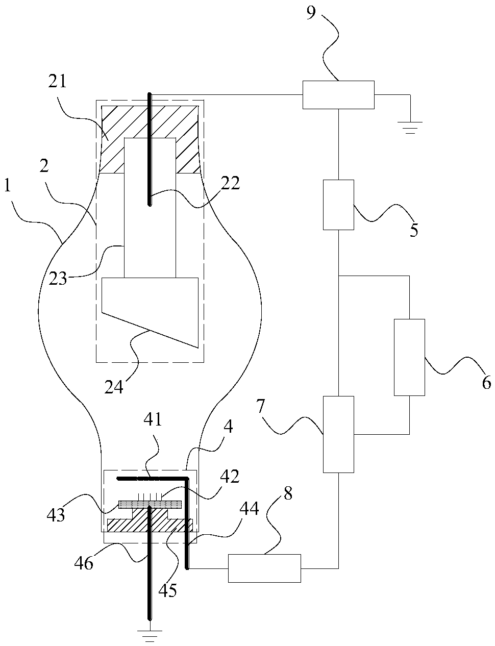
[0046] Please refer to figure 1 As shown, an integrated field emission X-ray source includes a field emission X-ray tube, a feedback control circuit capable of high-speed feedback modulation grid power supply and an auxiliary power supply, wherein the field emission X-ray tube includes a vacuum The container 1 and the anode target 2 and the electron gun installed in the vacuum container, the electron gun includes an emission cathode 4 and a grid 41, the emission cathode and the anode target are respectively installed at opposite ends of the vacuum container, and the grid The electrode is installed between the emitter cathode and the anode target; the anode target, emitter cathode and grid are respectively drawn out of the vacuum container through the anode target electrode 22, the emitter cathode electrode and the grid electrode 44.
[0047] The feedback control circuit includes an anode current sampling module 5, a scanning storage module 6, a nonlinear adjustment control mod...
Embodiment 2
[0067] The improvement that embodiment two carries out on the basis of embodiment one, has increased focusing lens 3 in its electron gun structure, please refer to Figure 6 and 7 As shown, a focusing lens is set between the grid and the anode target, and the focusing lens is one of a metal sleeve, a single electrostatic lens, a combination of multiple electrostatic lenses, and an electromagnetic lens; when the focusing lens is a metal sleeve, When one of a single electrostatic lens and a combination of multiple electrostatic lenses, the focusing lens is installed in the vacuum container and is located between the grid and the anode target; when the focusing lens is an electromagnetic lens, the focusing lens is installed outside the vacuum container, and Part or all of the magnetic field generated by the electromagnetic lens is located between the grid and the anode target, and the focusing lens is grounded or connected to a power supply through the focusing lens electrode 31 ...
Embodiment 3
[0070] Embodiment 3 is roughly the same as Embodiment 1, the difference is that this Embodiment 3 uses the auxiliary power supply of double-terminal positive and negative high voltage power supply, please refer to Figure 8 As shown, the connection mode of the double-terminal positive and negative high-voltage power supply is that the anode target electrode is connected to the positive high-voltage power supply, the emission cathode electrode is connected to the negative high-voltage power supply 10, and the gate is externally connected to the feedback control circuit. In this case, the gate voltage input module is suspended on the negative high-voltage power supply. The so-called suspension means that the gate voltage input module has two input terminals, one of which is connected to the output terminal of the nonlinear adjustment control module. The other input terminal is connected to the negative high-voltage power supply, that is, the negative high-voltage power supply is ...
PUM
 Abstract
Description
Claims
Application Information
 - R&D
- Intellectual Property
- Life Sciences
- Materials
- Tech Scout
- Unparalleled Data Quality
- Higher Quality Content
- 60% Fewer Hallucinations
Browse by: Latest US Patents, China's latest patents, Technical Efficacy Thesaurus, Application Domain, Technology Topic, Popular Technical Reports.
© 2025 PatSnap. All rights reserved.Legal|Privacy policy|Modern Slavery Act Transparency Statement|Sitemap|About US| Contact US: help@patsnap.com


