Method for detecting position of mask holder on measuring table

A technology of mask fixtures and masks, which is applied in the field of calibrating the measurement system used for this purpose, can solve the problems of measurement error, process error influence, fixture edge roughness, etc.

Active Publication Date: 2018-12-21
CARL ZEISS SMT GMBH
View PDF2 Cites 3 Cited by
  • Summary
  • Abstract
  • Description
  • Claims
  • Application Information

AI Technical Summary

Problems solved by technology

However, the process is subject to errors due to the manufacturing method, especially in the y-direction due to significant roughness or irregularities of the jig edges
If, due to placement tolerances of the mask fixture on the measurement table of the measurement system, the edges of the fixture are measured with different image parts during the measurement operation, significant measurement errors may thus arise

Method used


Image

  • Method for detecting position of mask holder on measuring table
  • Method for detecting position of mask holder on measuring table

Examples


Embodiment Construction

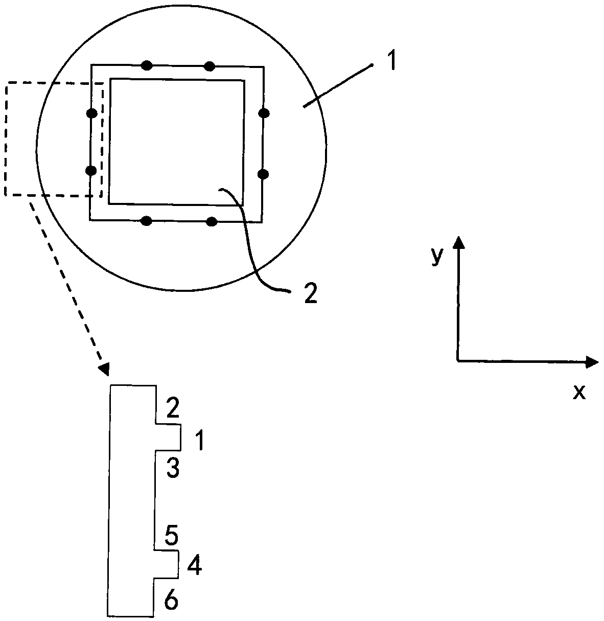
[0042] In the example schematic, figure 1 The mask holder 1 is shown with the mask 2 arranged therein on a three-point bearing not shown in the figure. Typically, a mask holder 1 is used to receive a mask 2 to be measured and to carry this mask 2 on a measurement table of a measurement system for the duration of the measurement, for successively regular reception of different masks. As already mentioned, precise knowledge about the position of the mask holder 1 on the measurement table is necessary for precise and reproducible measurements of structures on the mask 2 . However, a systematic error is involved in the establishment of the position of the mask holder 1 on the measurement table, which is due to the structure of the mask holder 1 itself. For the purpose of measuring the mask holder 1 on the measuring table, the measuring points shown in the figure but not respectively marked are used on the inner side of the mask holder 1 facing the mask 2 .

[0043] From the part...


PUM


Abstract

The invention relates to a method for detecting the position of a mask holder (1) for masks (2) for photolithography, comprising the following steps: Positioning the mask holder (1) with masks (2) ona measuring table of a measuring device; measuring the mask holder (1) by means of an algorithm; recording the absolute position of the mask holder (1) on the measuring table and capturing and recording at least one reference image.

Description

[0001] Cross References to Related Applications [0002] This application claims priority from German patent application DE 10 2016 107 524.8, the content of which is hereby incorporated by reference in its entirety. technical field [0003] The invention relates to a method of detecting the position of a mask holder of a mask for semiconductor lithography, and in particular a method of calibrating a measurement system used therefor. Within the scope of the production of semiconductor components, such masks usually contain structures (so-called patterns) which are imaged on a semiconductor substrate (so-called wafer). Background technique [0004] Within the scope of the aforementioned production and subsequent use of the mask, it is necessary to determine the absolute position of the pattern on the mask. For this purpose, coordinate measuring machines specially developed for this application are usually used. Commercially available from Carl Zeiss SMT GmbH is hereby desig...

Claims


Application Information

Patent Timeline
Patent Type & Authority Applications(China)
IPC IPC(8): G03F7/20G01B11/03G03F1/84H01L21/67G01N21/956
CPCG01B11/002G01N2021/95676G03F1/84G03F7/70691G03F7/70775G03F9/7011G06T7/001G06T2207/10056G06T2207/30148G06T7/12G06T7/74G01B11/005
Inventor H-M.索罗万
Owner CARL ZEISS SMT GMBH
Why Eureka
Try Eureka