
Crankshaft machining device and machining method

A kind of crankshaft processing and crankshaft technology, which is applied in the field of crankshaft processing devices, can solve the problems of small eccentricity of eccentric shaft section, low precision, complicated operation, etc., and achieve the effect of ensuring processing accuracy, improving work efficiency, and wide application prospects

Active Publication Date: 2018-12-25
CRRC QISHUYAN INSTITUTE CO LTD
View PDF8 Cites 0 Cited by
  • Summary
  • Abstract
  • Description
  • Claims
  • Application Information

AI Technical Summary

Problems solved by technology

However, most of these processing methods have low precision and low efficiency, are not suitable for batch processing, and lack a flexible and efficient top to cooperate with them. During processing, it is necessary to process a center hole and an eccentric center hole on the end face of the shaft. The position of the tip also needs to be adjusted during the shaft section, resulting in numerous procedures and complicated operations, making it difficult to guarantee the accuracy requirements
[0004] There are two or three crankshafts in the mainstream industrial robot reducers on the market. Due to the compact structure of the reducer, the machining accuracy of the parts is very high, so the requirements for the size and accuracy of the crankshaft are also very high. The eccentricity of the eccentric shaft section on the crankshaft Small, difficult to process

Method used


Image

  • Crankshaft machining device and machining method
  • Crankshaft machining device and machining method
  • Crankshaft machining device and machining method

Examples


Embodiment 1

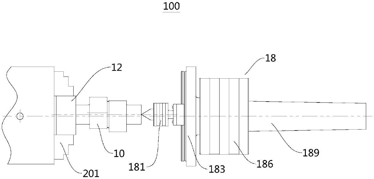
[0054] figure 1 A schematic structural view of the crankshaft processing device 100 provided by the present invention, such as figure 1 As shown, the crankshaft processing device 100 provided by Embodiment 1 of the present invention includes a crankshaft eccentric sleeve assembly 12 and an adjustable eccentric tip assembly 18 .

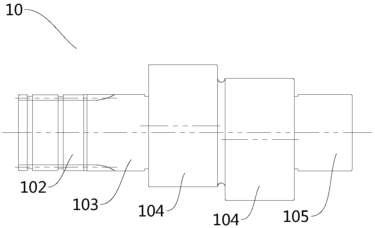
[0055] Use this crankshaft processing device 100 to process the crankshaft 10 to be processed, use the machine tool chuck 201 to clamp and fix one end of the crankshaft 10 to be processed through the crankshaft eccentric bushing assembly 12, and the other end of the crankshaft 10 to be processed is passed through the adjustable eccentric tip assembly 18 Clamping can realize high-efficiency and high-precision batch processing. The processed crankshaft 10 can be applied to industrial robot reducers with high processing accuracy and can effectively ensure the accuracy of eccentricity.

[0056] figure 2 is a structural schematic diagram of the cranksha...

Embodiment 2

[0087] Embodiment 2 of the present invention provides a crankshaft processing method for processing a crankshaft 10 having a spline shaft section 102 and a bearing installation section, and the specific description is as follows:

[0088] Preparatory steps: clamp the crankshaft 10 to be processed on the machine tool chuck 201 through the crankshaft eccentric bushing assembly 12, make the spline shaft section 102 cooperate with the spline collet 125, and place the Morse taper shank in the adjustable eccentric tip assembly 18 1896 installed in the taper hole of the lathe tailstock.

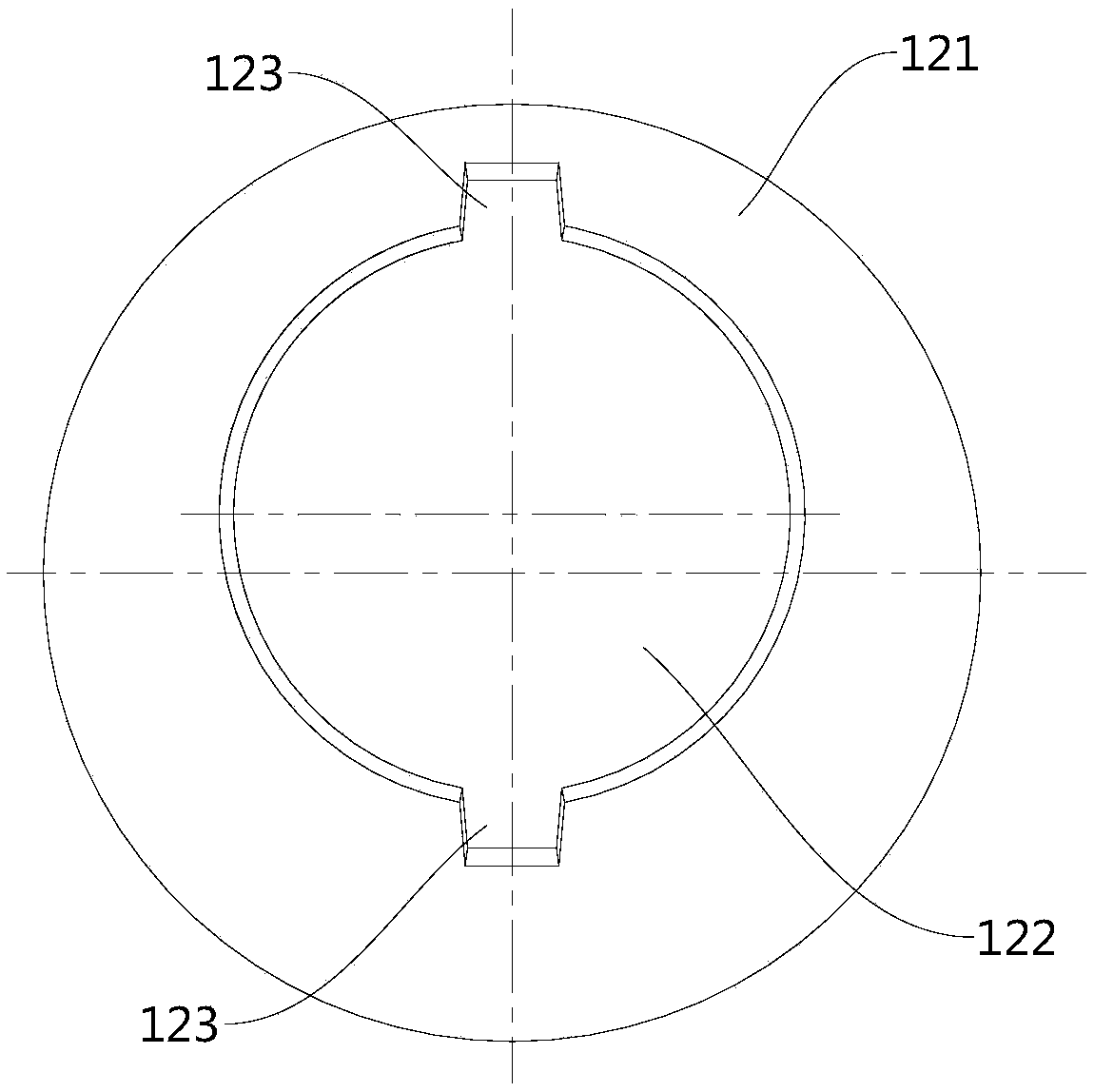
[0089] One end of the crankshaft 10 to be processed is assembled on the eccentric shaft sleeve 121, and then the whole is clamped in the chuck 201 of the machine tool, and the other end of the crankshaft 10 to be processed is tightened by the adjustable eccentric center. A first split groove 127 and a second split groove 128 are provided, the split groove communicates with the spline hole, the splin...


PUM


Abstract

The invention discloses a crankshaft machining device and a crankshaft machining method, and relates to the technical field of crankshaft machining. The crankshaft machining device comprises a crankshaft eccentric shaft sleeve component and an adjustable eccentric centre component, wherein the crankshaft eccentric shaft sleeve component comprises an eccentric shaft sleeve and a spline collet chuck; and the spline collet chuck is embedded to the eccentric shaft sleeve and is provided with a spline hole fixed to a crankshaft to be machined. The adjustable eccentric centre component comprises a rotary centre and a linear sliding rail component, wherein the rotary centre is glidingly arranged to the linear sliding rail component and comprises a centre matched with the crankshaft to be machined. The crankshaft machining device has the advantage of high positioning accuracy, can machine eccentric shaft sections at different phase angles, realizes rapid inserting and extracting, and improvesthe work efficiency.

Description

technical field [0001] The invention relates to the technical field of crankshaft processing, in particular to a crankshaft processing device and a processing method. Background technique [0002] A crankshaft is a part with two or more sections of outer circles on the same shaft whose centerlines are parallel and do not overlap. The crankshaft is widely used in various engines, reducers and other devices. Because of its unique structural features, it can realize various mechanical actions. It is a relatively common mechanical part in the field of mechanical design. According to the difference in eccentricity and design accuracy, its processing technology is also different. [0003] At present, the crankshaft processing methods commonly used in the domestic machining industry include the double-top method, the eccentric bushing method, and the three-jaw self-centering chuck plus gasket method. However, most of these processing methods have low precision and low efficiency, ...

Claims


Application Information

Patent Timeline
IPC IPC(8): B23B23/04B23B5/18B23B1/00
CPCB23B1/00B23B5/18B23B23/045
Inventor 唐亚辉常安全王晓雨
Owner CRRC QISHUYAN INSTITUTE CO LTD
Learn More