Foaming ceramic core composite material sandwich structure and forming method thereof

A foamed ceramic and sandwich structure technology, applied in chemical instruments and methods, synthetic resin layered products, layered products, etc. Simple processing and molding, low-density effect

Inactive Publication Date: 2018-12-25
WUHAN UNIV OF TECH
View PDF9 Cites 4 Cited by
  • Summary
  • Abstract
  • Description
  • Claims
  • Application Information

AI Technical Summary

Problems solved by technology

[0004] At this stage, there are few reports on the sandwich structure of foamed ...

Method used


Image

  • Foaming ceramic core composite material sandwich structure and forming method thereof
  • Foaming ceramic core composite material sandwich structure and forming method thereof

Examples


Embodiment 1

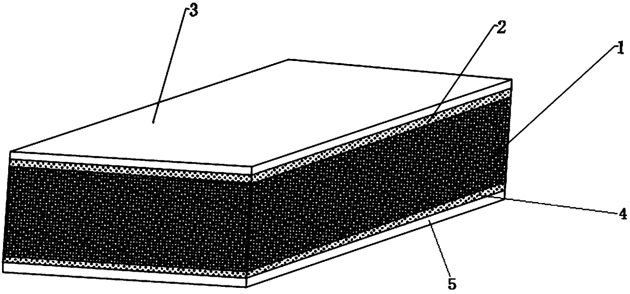
[0028] Example 1 A foamed ceramic core composite sandwich structure, prepared by the following method:

[0029] refer to figure 1 , a foamed ceramic core composite sandwich structure comprising a thickness of 40mm and a bulk density of 0.28g / cm 3 The foamed ceramic core material 1, the first glass fiber reinforced flame-retardant phenolic resin composite material plate 3 with a thickness of 5mm, the second glass fiber reinforced flame-retardant phenolic resin composite material plate 5 with a thickness of 5mm, and the foamed ceramic core material 1 and the first flame-retardant polymer bonding layer 2 between the first glass fiber reinforced flame-retardant phenolic resin composite material plate 3, the foamed ceramic core material 1 and the second glass fiber reinforced flame-retardant phenolic resin composite material plate 5 The second flame-retardant polymer adhesive layer 4 between them. The material of the first flame-retardant polymer adhesive layer 2 and the second f...

Embodiment 2

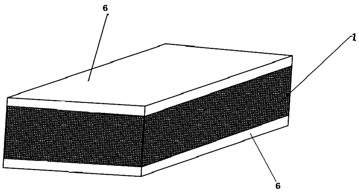
[0038] Embodiment 2 A foamed ceramic core composite sandwich structure, prepared by the following method:

[0039] refer to figure 2 , a foamed ceramic core composite sandwich structure comprising a thickness of 30mm and a bulk density of 0.56g / cm 3 The foamed ceramic core material 1 and the prepreg 6 of fiber-reinforced flame-retardant epoxy resin composite material located on the upper surface and the lower surface of the foamed ceramic core material 1 respectively. The molding method of this sandwich structure is: impregnating the fiber cloth with flame-retardant epoxy resin to form a prepreg 6 of fiber-reinforced flame-retardant epoxy resin composite material, and laying it on the upper surface and the lower surface of the foamed ceramic core material 1 respectively. The prepreg 6 of the fiber-reinforced flame-retardant epoxy resin composite material, so that the prepreg 6 of the fiber-reinforced flame-retardant epoxy resin composite material and the foamed ceramic core ...


PUM

PropertyMeasurementUnit
Bulk densityaaaaaaaaaa
Thicknessaaaaaaaaaa
Thicknessaaaaaaaaaa

Abstract

The invention discloses a foaming ceramic core composite material sandwich structure. The sandwich structure comprises a foaming ceramic core material, a first fiber reinforced flame-retardant composite material layer positioned on the upper surface of the foaming ceramic core material and a second fiber reinforced flame-retardant composite material layer positioned on the lower surface of the foaming ceramic core material. There are two types of the forming methods for the sandwich structure: 1, enabling the first and second fiber reinforced flame-retardant composite material layers to be bonded with the upper surface and the lower surface of the foaming ceramic core material by using a flame-retardant macromolecular bonder; and salifying; 2, laying the fiber reinforced flame-retardant composite material on the upper surface and the lower surface of the foaming ceramic core material, performing prepreg, and salifying. Foaming ceramic is used as a core material, and the fiber reinforced flame-retardant composite material is used as an outer-layer skin, so the difficult-flammable foaming ceramic core composite material sandwich structure with high rigidity is formed. The prepared sandwich structure is suitable for the application fields which need a high fire-proof grade and the high rigidity, such as fire-proof doors, building materials, subway escape platforms, and ocean engineering platforms.

Description

technical field [0001] The invention belongs to the field of composite materials, and in particular relates to a sandwich structure of a foamed ceramic core composite material and a forming method thereof. Background technique [0002] Foamed ceramics is a high-porosity inorganic porous ceramic body with a three-dimensional space grid structure. Its pore diameters range from nanometers to micrometers, and its porosity is between 20% and 95%. Its shape is like tempered. Styrofoam or porcelain foamed ceramic sponge. Due to its unique structure, it has the characteristics of high rigidity, low density, non-combustibility, non-water absorption, low thermal conductivity, thermal shock resistance, corrosion resistance, high temperature resistance, weather resistance, aging resistance, attraction, and sound insulation. It has been applied to Aviation, electronics, environmental protection, construction and other fields. [0003] At present, the sandwich structure of composite mat...

Claims


Application Information

Patent Timeline
IPC IPC(8): B32B9/00B32B9/04B32B27/06B32B27/04B32B7/12B32B27/20B32B27/42B32B27/38B32B27/30B32B27/40B32B33/00B29C70/30B29C70/34
CPCB29C70/30B29C70/34B29C2791/006B29K2061/04B29K2063/00B32B5/18B32B7/12B32B27/065B32B27/20B32B27/30B32B27/38B32B27/40B32B27/42B32B33/00B32B2250/03B32B2250/40B32B2260/021B32B2260/046B32B2262/0269B32B2262/101B32B2262/106B32B2262/14B32B2266/04B32B2307/3065B32B2307/536
Inventor 王钧代巍王浩杨小利苏晓岗段华军王翔
Owner WUHAN UNIV OF TECH
Why Eureka
Try Eureka