Deep-cooling air separation system of newly-added nitrogen producing tower

A technology of cryogenic air separation and nitrogen generating tower, which is applied in the direction of cold treatment separation, refrigeration and liquefaction, liquefaction, etc., which can solve the problems of poor energy consumption and achieve the effect of reducing configuration

Pending Publication Date: 2018-12-25
盈德气体工程(浙江)有限公司
View PDF0 Cites 3 Cited by
  • Summary
  • Abstract
  • Description
  • Claims
  • Application Information

AI Technical Summary

Problems solved by technology

The above two methods have many limitat

Method used


Image

  • Deep-cooling air separation system of newly-added nitrogen producing tower

Examples


Embodiment

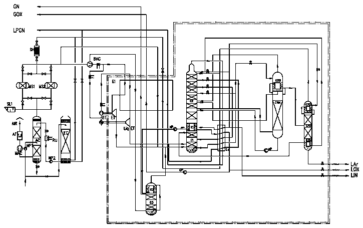
[0029] Example: figure 1 As shown, the present invention is a technological process of purifying air with molecular sieves, pressurizing air, compressing in an oxygen pump, cooling with a booster turbo expander, adopting a structured packing tower and fully rectifying hydrogen-free argon production.

[0030] Raw material air is inhaled from the suction port, dust and other mechanical impurities are removed through the self-cleaning air filter AF, the filtered air enters the centrifugal air compressor MAC, and after being compressed by the compressor, it enters the air cooling tower AC to be cooled; the upper part of the air cooling tower The chilled water enters, the middle part enters the circulating water at normal temperature, and the air passes through the air cooling tower AC from bottom to top, and is cleaned while being cooled.

[0031] After the circulating water enters the water-cooling tower, it is sent into the dirty nitrogen gas. Using the characteristic that the h...


PUM


Abstract

A deep-cooling air separation system of a newly-added nitrogen producing tower mainly comprises a molecular sieve purifier, an air booster, a booster expansion turbine, a structured packing tower anda full-rectification hydrogen-free argon producing tower. Air which is cooled by an air cooling tower enters the molecular sieve purifier which is switched to be used, the air booster continues to increase the pressure of a stream of feed air purified by the molecular sieve purifier and discharges two streams of air, and air which is pressurized by the air booster is discharged in two streams.

Description

technical field [0001] The invention relates to a cryogenic air separation system with a newly added nitrogen-making tower, belonging to the technical field of cryogenic air separation. Background technique [0002] With the development of the chemical industry, customers are using more and more nitrogen. In the traditional air separation process, it is first necessary to ensure the production of oxygen, and then two methods are generally used to deal with the larger nitrogen-oxygen ratio. One, increase Nitrogen compressor; Second, sacrifice the extraction rate of oxygen and argon to meet the nitrogen demand of customers as much as possible. The above two methods have many limitations and poor energy consumption. Therefore, if the process can be further studied and improved, on the premise of ensuring the oxygen production, on the one hand, reducing the number of nitrogen compressors, on the other hand, ensuring the extraction rate of oxygen and argon as much as possible, w...

Claims


Application Information

Patent Timeline
IPC IPC(8): F25J3/04
CPCF25J3/04187F25J3/04721F25J3/04866F25J2215/42F25J2215/58F25J2230/30F25J2230/40F25J2235/42F25J2245/42F25J2205/32F25J2205/34F25J3/04296F25J3/04387F25J3/04157F25J3/04709F25J3/04442
Inventor 张育哲王继超周雯何梅勇毛宝良姜昊刘强侯强刘海鹏缪剑剑孙雪
Owner 盈德气体工程(浙江)有限公司
Why Eureka
Try Eureka