Novel low-temperature plasma sterilizer

A low-temperature plasma and sterilizer technology, applied in sanitary equipment for toilets, water supply devices, buildings, etc., can solve the problems of reducing plasma sterilization efficiency, unsuccessful plasma ignition, etc., and achieve the effect of improving efficiency

Inactive Publication Date: 2018-12-28
华蓥市职业教育培训中心
View PDF5 Cites 3 Cited by
  • Summary
  • Abstract
  • Description
  • Claims
  • Application Information

AI Technical Summary

Problems solved by technology

[0005] The purpose of the present invention is to solve the problems that most of the above-mentioned current plasma sterilization equipments have unsuccessful plasma initiation, which often leaves hidden dangers for plasma sterilization, or reduces the efficiency of plasma sterilization. The present invention provides a New Low Temperature Plasma Sterilizer

Method used


Image

  • Novel low-temperature plasma sterilizer

Examples


Embodiment 1

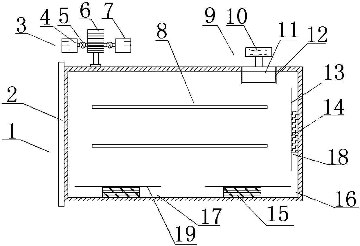
[0032] Such as figure 1 As shown, a new low-temperature plasma sterilizer includes a sterilizer body 1 and a front cover 2, and is characterized in that: the sterilizer body 1 includes a vacuum device 3, a liquid injection diffusion device 9 and a sterilization generating device 16 , the sterilization generating device 16 includes a DC sterilizing device 18 connected to a DC power source and a radio frequency sterilizing device 17 connected to an AC power source, the DC sterilizing device 18 includes a DC electrode 14 and a second electrode connected to the DC electrode 14 A metal mesh 13 , the radio frequency sterilizing device 17 includes a radio frequency electrode 15 and a second metal mesh 19 communicated with the radio frequency electrode 15 .

[0033] The working principle and process of this technical solution are as follows:

[0034] When using the present invention, open the front cover 2, wrap the medical instruments that need to be sterilized with non-woven fabric...

Embodiment 2

[0037] According to Example 1, such as figure 1 As shown, the vacuum device 3 includes an air inlet filter 4, an air outlet filter 7, and a vacuum pump 6 that is positioned between the air inlet filter 4 and the air outlet filter 7 and is connected through a trachea. The air exchange port located on the top surface of the sterilizer body 1 is connected. The setting of air inlet filter 4 can prevent impurity gas from entering in the sterilizer body 1 during air intake, and the setting of air outlet filter 7 can prevent that toxic gas is discharged into the air during air extraction.

Embodiment 3

[0039] According to embodiment 2, such as figure 1 As shown, ventilation valves 5 are provided between the air inlet filter 4 and the vacuum pump 6 and between the air outlet filter 7 and the vacuum pump 6 . The setting of the ventilation valve 5 helps to control the suction and intake of the vacuum pump 6 .


PUM


Abstract

The invention relates to a novel low-temperature plasma sterilizer which comprises a sterilizer body and a front cover, wherein the sterilizer body comprises a vacuum device, an injection diffusion device and a sterilization generation device, wherein the sterilization generation device comprises a direct-current sterilization device which is connected with a direct-current power supply and a radio frequency sterilization device which is connected with an alternative-current power supply; the direct-current sterilization device comprises a direct-current electrode and a first metallic net which is communicated with the direct-current electrode; the radio frequency sterilization device comprises radio frequency electrodes and second metallic nets communicated with the radio frequency electrodes. The direct-current sterilization device and the radio frequency sterilization device are creatively and simultaneously arranged in the novel low-temperature plasma sterilizer provided by the invention, the direct-current sterilization device is powered on to operate for a certain time before the radio frequency sterilization device is powered on, brush discharge is firstly implemented, the two radio frequency electrodes are liable to build up luminance at a state that a gas in the sterilizer body builds up luminance, then generation of uniform large-area plasma can be ensured, and the plasma sterilization efficiency can be improved.

Description

technical field [0001] The invention relates to the technical field of sterilization and disinfection equipment, in particular to a novel low-temperature plasma sterilizer. Background technique [0002] At present, the sterilization of various items that are afraid of heat and humidity are used in hospitals, such as endoscopes, pacemakers, artificial valves, optical instruments, electronic equipment, catheters, plastic products, etc. must be sterilized, but these instruments Most of them will be deformed at high temperature, so it is not suitable to use conventional high-temperature methods for sterilization, and high-temperature sterilization will shorten the service life of expensive medical devices. If the method of soaking in disinfectant is used, it is often impossible to completely kill the bacteria in the gaps of the instruments, and there will be residues left on the instruments after sterilization, and the sterilization cycle is long. [0003] In the plasma state, ...

Claims


Application Information

Patent Timeline
Patent Type & Authority Applications(China)
IPC IPC(8): A61L2/14A61L2/26
CPCA61L2/14A61L2/26
Inventor 董建军
Owner 华蓥市职业教育培训中心
Why Eureka
Try Eureka