
Microwave heating adsorption and desorption tank and application thereof in environmental protection field of VOCs

A microwave heating and microwave heater technology, applied in gas treatment, membrane technology, dispersed particle separation, etc., can solve the problems of high operating energy consumption, large investment in process equipment, secondary pollution, etc., and achieve low operating costs, desorption and desorption. Good effect and low operating pressure

Inactive Publication Date: 2018-12-28
魏智广
View PDF7 Cites 1 Cited by
  • Summary
  • Abstract
  • Description
  • Claims
  • Application Information

AI Technical Summary

Problems solved by technology

[0003] At present, microporous materials such as activated carbon and activated carbon fiber are generally used for adsorption treatment of volatile organic waste gas, and then high-temperature steam is used to desorb organic solvents from the saturated microporous materials. However, this process requires a large amount of Consumption of water vapor, at the same time, after the separation of solvent and water, a large amount of waste water will be generated to be further treated, the whole process is complex, the investment in process equipment is large, secondary pollution is easy to occur, energy is wasted, and energy consumption is high in operation
At the same time, due to the increasingly severe atmospheric environment, the high pollution generated by boilers also makes the country implement strict control over boiler construction, and the large demand for water vapor has also become a constraint for the promotion of existing volatile organic waste gas purification technology.

Method used


Image

  • Microwave heating adsorption and desorption tank and application thereof in environmental protection field of VOCs
  • Microwave heating adsorption and desorption tank and application thereof in environmental protection field of VOCs
  • Microwave heating adsorption and desorption tank and application thereof in environmental protection field of VOCs

Examples


Embodiment 1

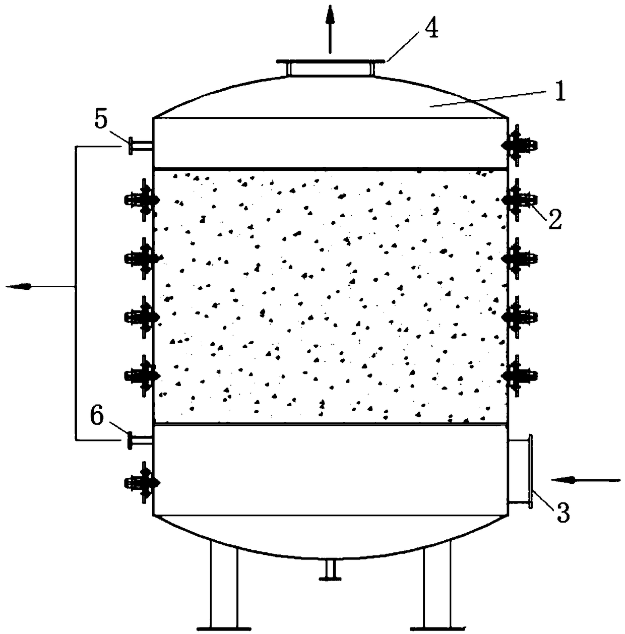
[0030] The invention provides a microwave heating adsorption-desorption tank and its application in the field of environmental protection Vocs treatment and its application. The microwave heating absorption-desorption tank includes a tank body 1, an adsorbent bed and a microwave heater 2;

[0031] The side wall of the tank body 1 is provided with an exhaust gas inlet 3 near the bottom, and the top is provided with an exhaust gas outlet 4. The side wall is provided with an upper steam outlet 5 and a lower steam outlet 6; an exhaust gas inlet 3, an exhaust gas outlet 4, and a steam upper outlet The outlet 5 and the lower steam outlet 6 are respectively provided with valves; the microwave heaters 2 are evenly distributed on the outer wall of the tank body 1 to form a microwave heating system;

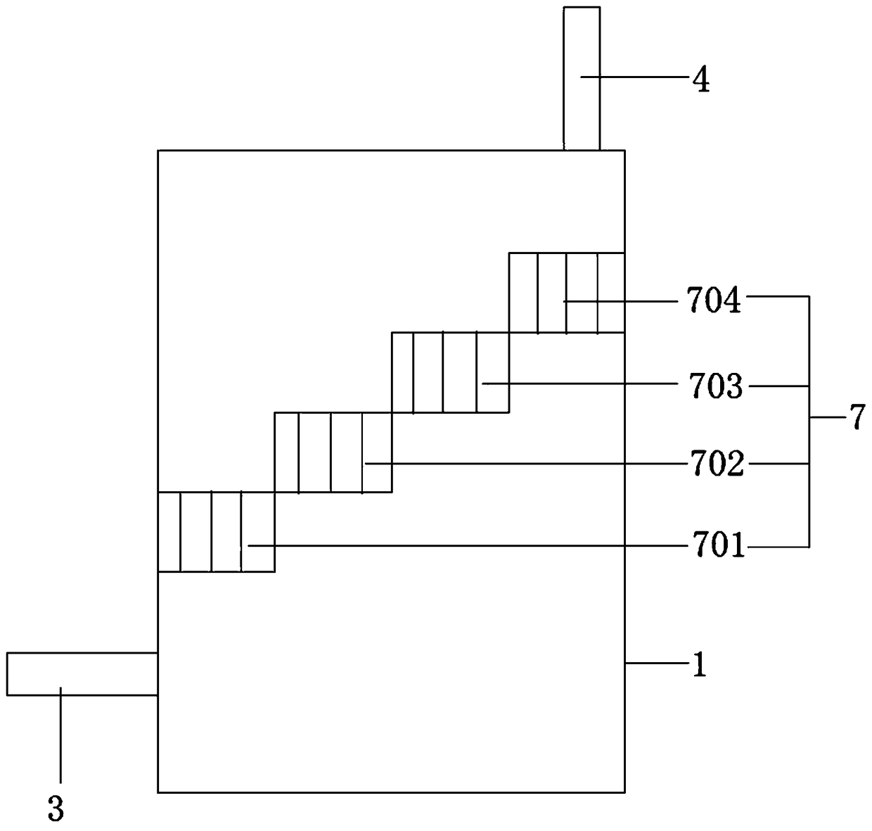
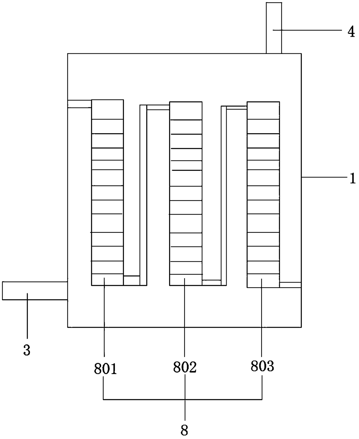
[0032] There are several adsorbent beds inside the tank body 1; the exhaust gas inlet 3 is located upstream of the adsorbent bed, and the adsorption bed includes a skeleton with holes and a...

Embodiment 2

[0035] The invention provides a microwave heating adsorption-desorption tank and its application in the field of environmental protection Vocs treatment. The microwave heating absorption-desorption tank includes a tank body 1, an adsorbent bed and a microwave heater 2;

[0036] The side wall of the tank body 1 is provided with an exhaust gas inlet 3 near the bottom, and the top is provided with an exhaust gas outlet 4. The side wall is provided with an upper steam outlet 5 and a lower steam outlet 6; an exhaust gas inlet 3, an exhaust gas outlet 4, and a steam upper outlet The outlet 5 and the lower steam outlet 6 are respectively provided with valves; the microwave heaters 2 are evenly distributed on the outer wall of the tank body 1 to form a microwave heating system;

[0037] There are several adsorbent beds inside the tank body 1; the exhaust gas inlet 3 is located upstream of the adsorbent bed, and the adsorption bed includes a skeleton with holes and an adsorbent attached...

Embodiment 3

[0040] The invention provides a microwave heating adsorption-desorption tank and its application in the field of environmental protection Vocs treatment. The microwave heating absorption-desorption tank includes a tank body 1, an adsorbent bed and a microwave heater 2;

[0041] The side wall of the tank body 1 is provided with an exhaust gas inlet 3 near the bottom, and the top is provided with an exhaust gas outlet 4. The side wall is provided with an upper steam outlet 5 and a lower steam outlet 6; an exhaust gas inlet 3, an exhaust gas outlet 4, and a steam upper outlet The outlet 5 and the lower steam outlet 6 are respectively provided with valves; the microwave heaters 2 are evenly distributed on the outer wall of the tank body 1 to form a microwave heating system;

[0042] There are several adsorbent beds inside the tank body 1; the exhaust gas inlet 3 is located upstream of the adsorbent bed, and the adsorption bed includes a porous framework and an adsorbent attached to t...


PUM


Abstract

The invention provides a microwave heating adsorption and desorption tank for environmental protection treatment of VOCs. The microwave heating adsorption and desorption tank comprises a tank body, adsorbent bed layers and microwave heaters, wherein a waste gas inlet is formed in the side wall, close to the bottom end, of the tank body; a waste gas outlet is formed in the top end of the tank body;an upper steam outlet and a lower steam outlet are formed in the side wall of the tank body; valves are respectively arranged on the waste gas inlet, the waste gas outlet, the upper steam outlet andthe lower steam outlet; the microwave heaters are uniformly distributed on the outer wall of the tank body to form a microwave heating system; the tank body is internally provided with a plurality ofadsorbent bed layers; the waste gas inlet is positioned on the upstream of the absorbent bed layers. According to the microwave heating adsorption and desorption tank provided by the invention, adsorbed VOCs can be treated by combining reduced pressure desorption with microwave heating; the desorption effect is better, an adsorbent is protected more easily and the service life of the adsorbent isprolonged.

Description

technical field [0001] The invention relates to the technical field of organic waste gas purification, in particular to a microwave heating absorption and desorption tank and its application in the field of environmental protection Vocs treatment. Background technique [0002] With the wide application of organic chemical products in industry, more and more volatile organic pollutants enter the atmosphere, mainly low boiling point and volatile organic compounds. They mainly come from waste gas emitted by the petrochemical industry; flexible packaging printing, pesticides, pharmaceutical intermediates, automotive spraying, electronics, machinery, shoemaking, synthetic leather, synthetic fibers, plastics, papermaking, paints, coatings, ceramics, mining and textiles The organic solvents emitted by many industries, such as industrial plants, not only endanger the health of workshop workers and the surrounding people, cause air pollution, but also cause loss and waste of resource...

Claims


Application Information

Patent Timeline
IPC IPC(8): B01D53/04
CPCB01D53/0407B01D2253/102B01D2257/708B01D2258/02B01D2259/4009B01D2259/40094B01D2259/404B01D2259/4061
Inventor 魏智广
Owner 魏智广
Learn More