Wave power generation device with rope structure

A wave power generation and rope technology, which is applied to ocean energy power generation, engine components, machines/engines, etc., can solve the problems of low wave energy recovery rate, increase the size of power generation devices, and difficult protection, etc., and achieve high wave energy recovery rate. Low input-output ratio and good protection

Active Publication Date: 2019-01-01
YANSHAN UNIV
View PDF5 Cites 2 Cited by
  • Summary
  • Abstract
  • Description
  • Claims
  • Application Information

AI Technical Summary

Problems solved by technology

Among them, the energy-absorbing mechanism of the ocean wave power generation device based on the series structure is mostly a single-degree-of-freedom mechanism. Due to its small degree of freedom, it cannot make full use of the movement of waves, resulting in a low recovery rate of wave energy for this type of power generation device.
The energy-absorbing mechanisms of marine wave power generation devices based on parallel structures all adopt multi-degree-of-freedom mechanisms, which can well adapt to the multi-degree-of-freedom compound motion of ocean waves; however, most of these power generation devices rely on the reciprocating motion of the telescopic rod in the energy-absorbing mechanism to recover energy , in the design process, in order to make the power generation device adapt to the seasonal changes of wave height, the limit stroke of the telescopic rod needs to be designed very large. In this way, not only the volume of the power generation device is increased, but also the manufacturing cost of the power generation device is increased. , which also reduces the utilization efficiency of the power generation device; in addition, the energy recovery and conversion components of this type of power generation device are relatively close to the seawater and move in real time with the waves, which are not easy to protect and are easily corroded by seawater, thus reducing their reliable operation. sex and working life

Method used


Image

  • Wave power generation device with rope structure
  • Wave power generation device with rope structure
  • Wave power generation device with rope structure

Examples


Embodiment Construction

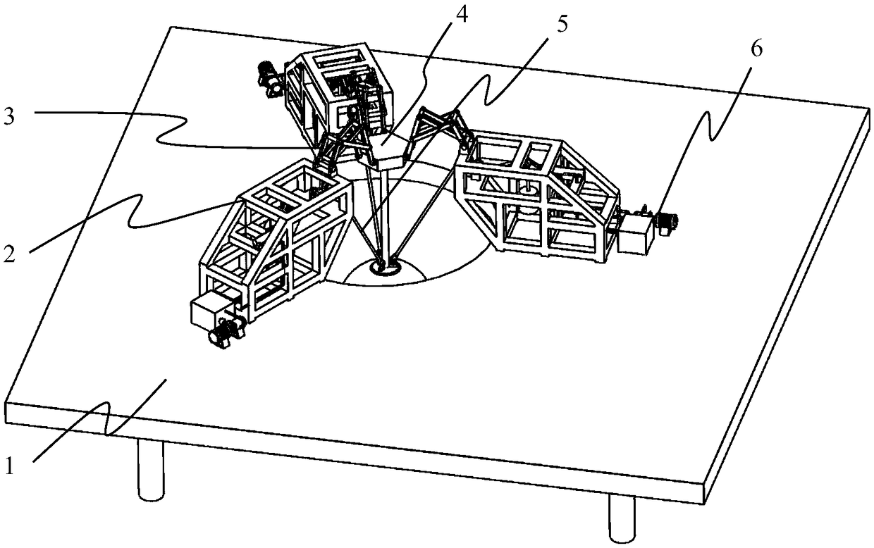
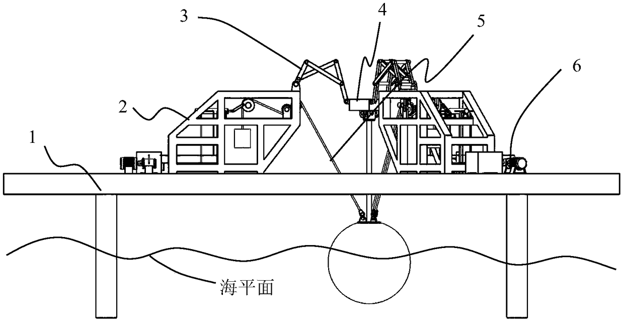
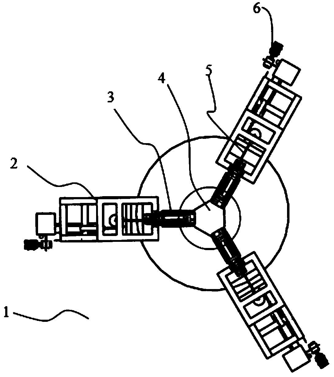
[0026] exist Figure 1 to Figure 8 In the schematic diagram of the present invention shown, the frame assembly 2 mainly includes three frame members 7 with the same structure and uniformly distributed along the circumferential direction, a hydraulic cylinder 34, a third oil inlet 47, a third oil outlet 46, The fourth oil inlet 48, the second oil outlet 45, and the hydraulic cylinder support 8 are provided with a front beam, a rear end beam and an intermediate beam inside the frame member, and the hydraulic cylinder 34 is fixed on the frame member 7 through the hydraulic cylinder support 8. on the rear beam. The front end of the hydraulic cylinder 34 is provided with a third oil inlet 47 and a third oil outlet 46, and the rear end of the hydraulic cylinder 34 is provided with a fourth oil inlet 48 and a second oil outlet 45. Check valves are installed respectively, so that the third oil inlet 47 and the fourth oil inlet 49 can only enter oil, and the second oil outlet 45 and t...


PUM


Abstract

The invention discloses a wave power generation device with a rope structure. The wave power generation device mainly comprises a machine frame assembly, a floating platform assembly, three evenly-distributed driven constraint branched chains, three rope branched chains and a hydraulic power generation system, wherein the three driven constraint branched chains are installed on the machine frame assembly and are of the same structure, and the three rope branched chains are of the same structure and are evenly distributed in the circumferential direction. Main movement of waves is converted into moving and swing of floaters, the floaters drive a rope to move, then, moving and swing are converted into rotation of a crank disc, and the wave power generation device can well adapt to wave movement, is not restricted by the wave height, and has the advantages that subjected impact force is small, the wave energy recycling rate is high, the structure is simple, the input-output ratio is low,protection performance is good, and manufacturability is good.

Description

technical field [0001] The invention relates to the technical field of power generation, in particular to a marine wave energy power generation device. Background technique [0002] The ocean accounts for about 71% of the earth's area. Due to the influence of air pressure and sea wind, waves are generated on the surface of the ocean almost all the time. This regular and periodic undulating movement of seawater contains enormous energy. As problems such as "global warming" and "energy depletion" become increasingly prominent, international scholars pay more and more attention to the recovery and utilization of this new type of renewable energy. [0003] After years of development, many wave energy generating devices have been proposed. Most of these wave power generation devices adopt a series or parallel structure. Among them, the energy-absorbing mechanism of the ocean wave power generation device based on the series structure is mostly a single-degree-of-freedom mechani...

Claims


Application Information

Patent Timeline
Patent Type & Authority Applications(China)
IPC IPC(8): F03B13/18F15B1/02
CPCF03B13/189F15B1/02Y02E10/30
Inventor 金振林赵裕明张金柱
Owner YANSHAN UNIV
Why Eureka
Try Eureka