A multifunctional valve hydraulic characteristics and cavitation performance test device

A technology of hydraulic characteristics and testing equipment, which is applied in the direction of measuring equipment, mechanical valve testing, mechanical parts testing, etc., can solve the problems of single function, inconvenient real-time comparison test of multiple valves, high pressure accuracy requirements, etc., to simplify the installation steps , Reduce test time cost, improve test efficiency

Active Publication Date: 2020-09-04
NANJING HYDRAULIC RES INST
View PDF6 Cites 0 Cited by
  • Summary
  • Abstract
  • Description
  • Claims
  • Application Information

AI Technical Summary

Problems solved by technology

[0007] Without exception, the above valve test devices can only test a single valve, which is not convenient for instant comparison tests of multiple valves, or multi-working condition tests of the same valve
The defect of the prior art is that the valve test device is a single-line design with a single function, and a single test can only be carried out for one valve and one working condition.
There is no such design in the known technology
Especially in the cavitation critical test of the valve, the precision of the pressure is very high, and the existing devices cannot accurately obtain the primary cavitation number of the valve.

Method used


Image

  • A multifunctional valve hydraulic characteristics and cavitation performance test device
  • A multifunctional valve hydraulic characteristics and cavitation performance test device
  • A multifunctional valve hydraulic characteristics and cavitation performance test device

Examples


Embodiment 1

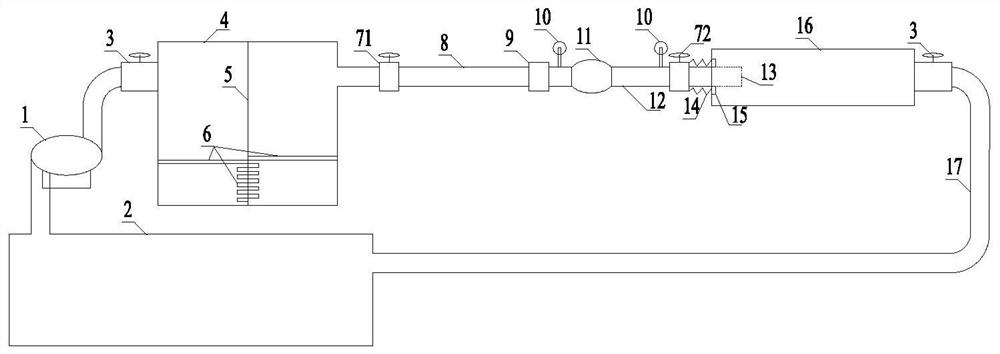
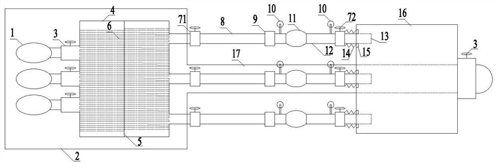
[0048] Taking three pumps and three valves as an example, the specific arrangement of the present invention is the same as figure 1 with 2 . The test device mainly includes: water supply section, test section and return water section.

[0049] The water supply section mainly includes: centrifugal pump 1; circulating reservoir 2; regulating valve 3;

[0050] There are 3 centrifugal pumps, which are driven by 380v motors. Among them, the head of the centrifugal pump needs to be ≥150m head; the inner radius R of the regulating valve 3 1 = 150mm. Circulating reservoir capacity > test system full load capacity + rich water depth capacity (rich water depth 1m) = 16m3 + 16m3 = 32m3 (circulating reservoir length × width × height = 4m × 4m × 2m); the control accuracy of the flow control valve is 0.01Mpa; The control parameters of the voltage stabilizing box are: valve spacing D = 2R 1 =300mm; the length of the surge tank in front of the valve L=6R 1 =900mm; the height of the pre...

Embodiment 2

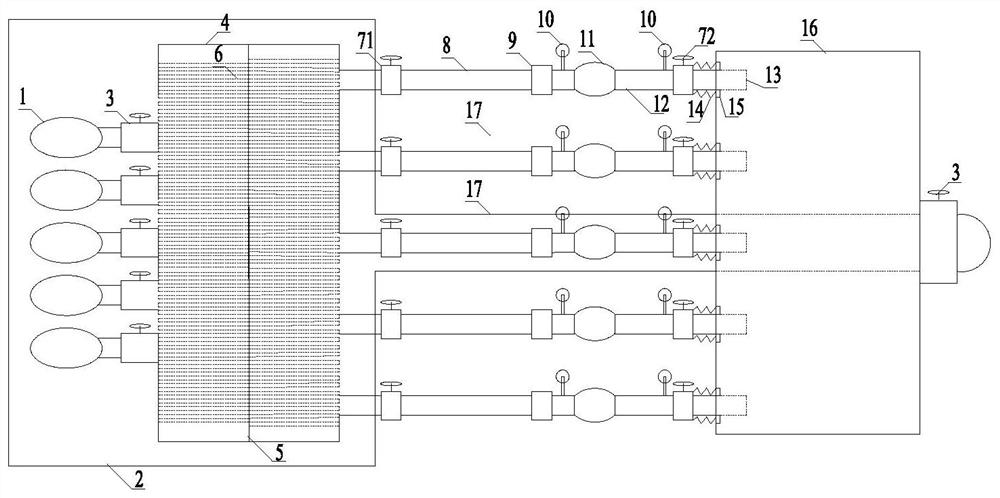
[0063] Taking five pumps and five valves as an example, the specific arrangement of the present invention is the same as figure 1 with 3 . The test device mainly includes three parts: water supply section, test section and return water section.

[0064] The water supply section mainly includes: centrifugal pump 1; circulating reservoir 2; regulating valve 3; There are 5 centrifugal pumps, which are driven by 380v motors. Among them, the head of the centrifugal pump needs to be ≥150m head; the inner radius R of the regulating valve 3 1 = 150 mm. Circulating reservoir capacity > test system full load capacity + rich water depth capacity (rich water depth 1m) = 22m 3 +16m 3 =38m 3 (Length × width × height of the circulating reservoir = 4m × 4m × 2.6m); the control accuracy of the flow regulating valve is 0.01Mpa; the control parameters of the pressure stabilization box before the valve are: valve distance D = 2R 1 =300mm; the length of the surge tank in front of the valve...


PUM


Abstract

The invention, which belongs to the valve testing field, relates to a multi-function hydraulic characteristic and cavitation performance test device of a valve. The test device comprises a water supply section, a test section and a backwater section. The test device has the following beneficial effects: on the basis of a multi-pump drive design, more test work conditions including high pressure drop and large flow conditions for cavitation testing can be provided for valve testing; the test conditions of the valve test work section become stable and precise; multi-valve testing can be carriedout simultaneously and conveniently, so that the test time is shortened; the water flow state and the cavitation phenomenon after the valve test can be observed conveniently; and the testing valve installation process is simplified.

Description

technical field [0001] The invention relates to a valve test device, in particular to a multifunctional valve hydraulic characteristic and cavitation performance test device, which belongs to the field of valve tests. Background technique [0002] In a fluid system, a valve is a general term for devices that control the flow of fluid media and regulate the flow and pressure of fluid media. Valves come in various shapes and types and are widely used. Its functions mainly include cutting off or connecting the medium, controlling and adjusting the flow rate, controlling the flow direction, preventing backflow, controlling or releasing the pressure, etc. For example, in the field of water conservancy and water transportation projects, there are many types of valves for the characteristics of water conservancy and water transportation projects. Flat door, arc door, reverse arc door and other valve types have a long application history, piston flow control valve, sleeve flow con...

Claims


Application Information

Patent Timeline
Patent Type & Authority Patents(China)
IPC IPC(8): G01M13/003
CPCG01M13/00
Inventor 胡亚安王蛟李中华王新李学义傅陆志丹
Owner NANJING HYDRAULIC RES INST
Why Eureka
Try Eureka