Multifunctional fuel magnetizer

A magnetizer and multi-functional technology, applied in the direction of combustion engine, machine/engine, internal combustion piston engine, etc., can solve the problems of unsmooth exhaust, cavitation, insufficient magnetization effect, etc., to improve the utilization rate of magnetic energy and reduce exhaust emissions , to avoid the effect of fuel corrosion

Pending Publication Date: 2019-01-04
梁严
View PDF1 Cites 2 Cited by
  • Summary
  • Abstract
  • Description
  • Claims
  • Application Information

AI Technical Summary

Problems solved by technology

[0003] 1. Generally, the oil supply pipe diameter of the fuel engine is small (about ∮10mm~∮14mm). Compared with the oil supply pipe, Figure 5 In the form of the built-in magnetic ring shown, the larger the magnet (when the oil passage gap is relatively constant), the larger the diameter, and the slower the flow rate during magnetization. On the contrary, if you want to increase the flow rate, the magnet must be reduced, and the relative magnetic strength will be reduced. Therefore, this form of magnetizer is limited by the diameter of the oil supply pipe of the fuel engine, and the magnetic strength and flow rate cannot be achieved at the same time. Due to the limitation of the pipe diameter, Image 6 The form of the external magnetic block shown cannot obtain higher magnetic strength;
[0004] 2. The fluid only passes through the magnetization device once, and then it will no longer be "cut" by the magnetic force lines, the stroke is short, and the magnetization effect is not ideal;
[0005] 3. Substances that are easily adsorbed by magnetism block the diameter of the oil supply pipe, and there is no emptying device, so the air in the fuel is easy to cause damage to the oil circuit (cavitation);
[0006] 4. There are some existing magnetizers equipped with an exhaust valve. The exhaust valve is only a small hole drilled on the metal structure, without plastic elastic deformation, easy to block, and the exhaust is not smooth.
[0007] The invention patent with the notification number CN101004158A increases the magnetic strength by setting multiple magnetic blocks coaxially, and makes the flow speed faster by reducing the width of the oil passage. Although the magnetization effect can be enhanced to a certain extent, the fluid flows through the passage once. It will flow out immediately after that, the magnetization effect is still insufficient, and there is no sewage interception or emptying device, which will easily cause blockage of the oil circuit, especially the narrow channel in the second half of the oil circuit

Method used


Image

  • Multifunctional fuel magnetizer
  • Multifunctional fuel magnetizer
  • Multifunctional fuel magnetizer

Examples


Embodiment 1

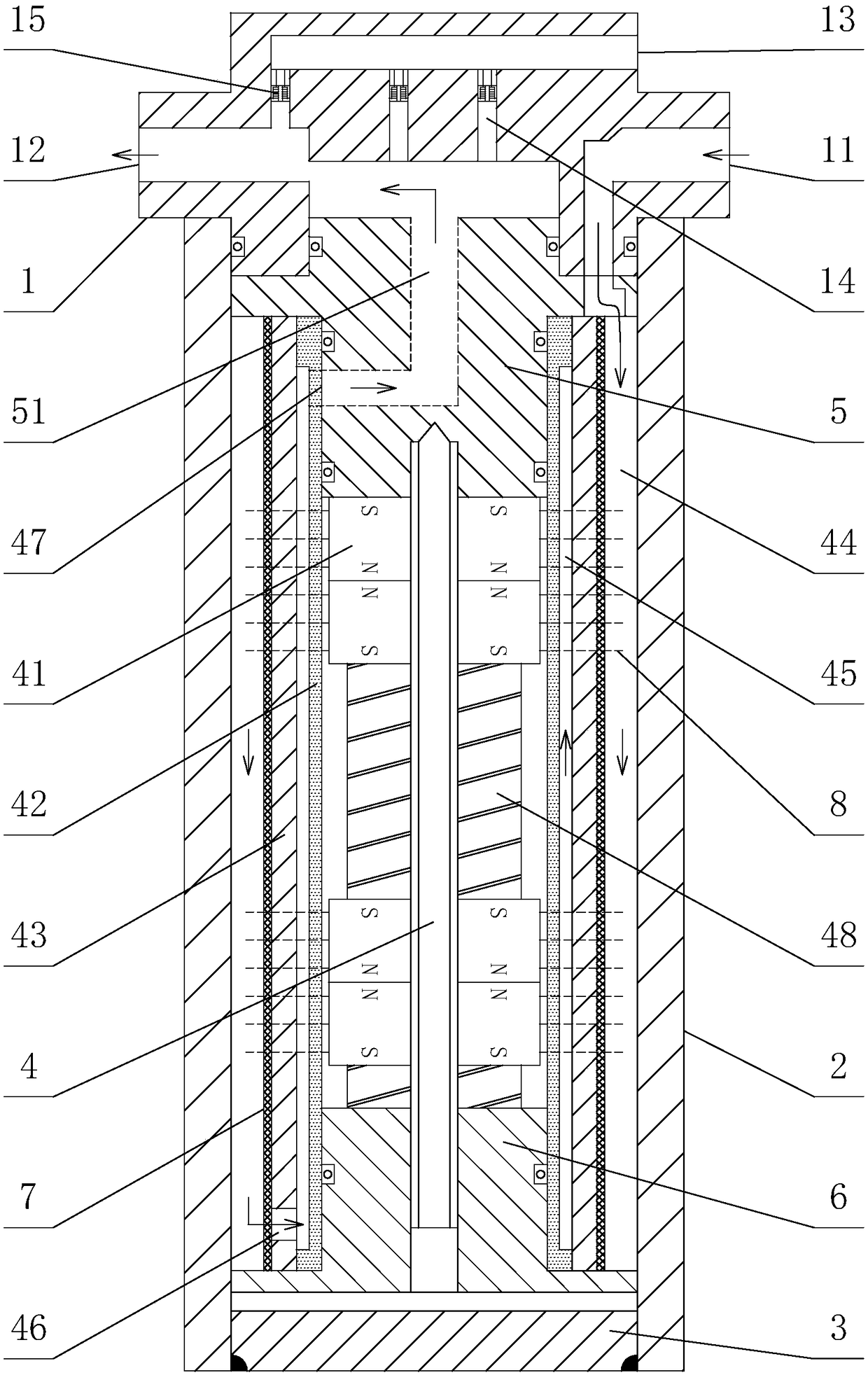
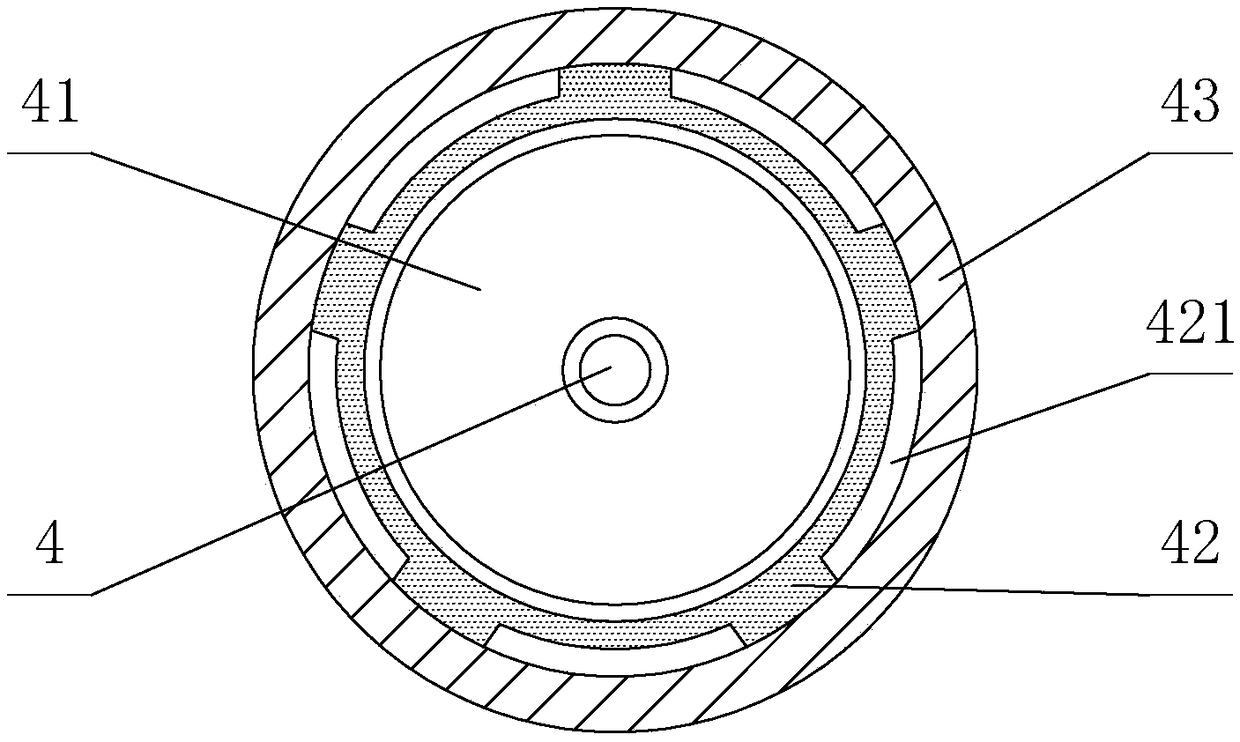
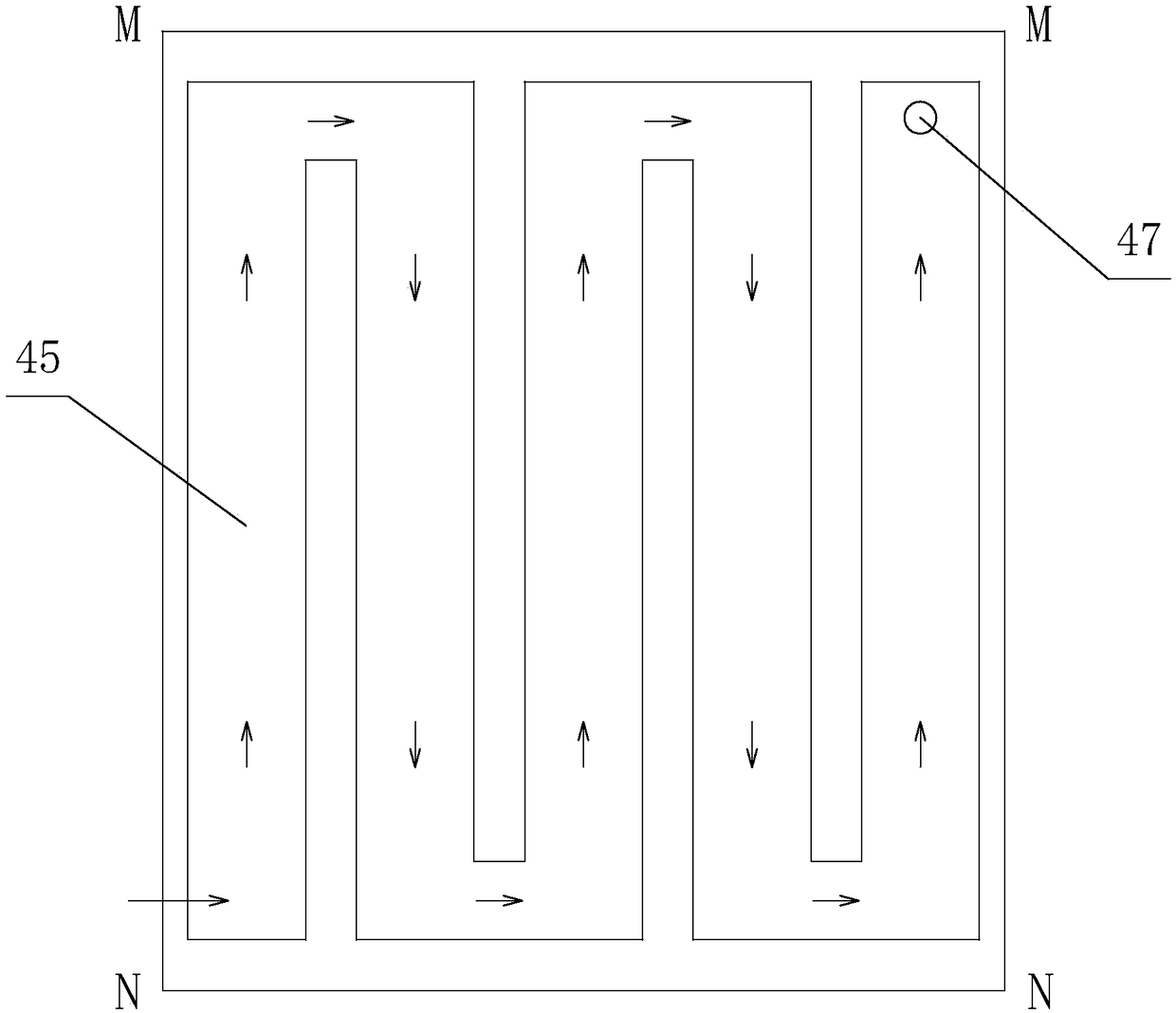
[0029] A multifunctional fuel magnetizer, such as figure 1 As shown, it includes an end cap 1, an outer cylinder body 2, an outer cylinder body rear cover 3 and a magnetization device, the outer cylinder body 2 is a cylinder, and the end cap 1 and the outer cylinder body rear cover 3 are respectively assembled on the outer cylinder The upper and lower ends of the body 2, the magnetization device is arranged in the outer cylinder body 2, the outer oil inlet 11 connected with the outlet of the oil pump and the outer oil outlet 12 connected with the engine fuel injection nozzle are arranged on the end cover 1, the magnetization The upper end of the device is connected to the end cover 1 through the core cover connecting body 5, and the lower end is pressed tightly in the outer cylinder body 2 by a core body back cover 6. The core cover connecting body 5 is provided with a fuel inner passage 51, and the fuel inner passage 51 is connected to the The external oil outlet 12 of the e...

Embodiment 2

[0036] A multifunctional fuel magnetizer, the structure of which is basically the same as that of Embodiment 1, the difference is that there are 1, 3 or several groups of magnetic energy cores, and 2 or 4 exhaust pipes and exhaust valves. indivual.


PUM


Abstract

A multifunctional fuel magnetizer comprises an end cover, an outer barrel, an outer barrel rear cover and a magnetizing device arranged in the outer barrel; the upper end of the magnetizing device isconnected to the end cover through a core cover connecting body; the lower end of the magnetizing device is tightly pressed into the outer barrel through a core body rear cover; the magnetizing devicecomprises a central screw, a magnetic energy core body, a magnetic permeable core body tube and a core body protection sleeve which are sequentially connected from inside to outside in a nesting mode; a cavity between the core body protection sleeve and the outer barrel forms a dirt intercepting cavity; the magnetic permeable core body tube and the core body protection sleeve are in close fit andare magnetically permeable; and the outer surface of the magnetic permeable core body tube is provided with a groove which is repeatedly circuitous up and down, and a magnetizing cavity is formed. Apermanent magnet ring body is isolated from fuel, the permanent magnet ring body is effectively prevented from being corroded by the fuel, the large-sized permanent magnet ring body can be arranged, the fuel passes through the magnetizing cavity and is repeatedly cut through magnetic lines of force, the oil channel passing cross-sectional area is adjusted by controlling the depth and width of thegroove, the fluid flow rate is increased, and the high magnetic strength and high flow rate are both achieved, so that the best magnetizing effect and combustion effect are achieved.

Description

technical field [0001] The invention relates to the technical field of fuel magnetization for engines, in particular to a multifunctional fuel magnetizer. Background technique [0002] At present, the fuel magnetizer has become an important way to reduce emissions and save energy for diesel engines. The fuel magnetization is actually "cutting" by the magnetic force lines when the fluid passes through the magnetic force lines perpendicular to the flow direction. The "cutting" effect is related to the magnetic strength of the magnetic force lines and the fluid flow velocity It is directly proportional to the higher the magnetic strength and the faster the flow rate, the better the effect. The fuel magnetizers currently in use are generally in the form of built-in magnetic rings or external magnetic blocks, that is, a magnetic ring is set inside the oil supply pipe of the fuel engine or in the A magnetic block is set outside the oil supply pipe, respectively as Figure 5 , Fi...

Claims


Application Information

Patent Timeline
Patent Type & Authority Applications(China)
IPC IPC(8): F02M27/04
CPCF02M27/045Y02T10/12
Inventor 梁严
Owner 梁严
Why Eureka
Try Eureka