Vehicle-mounted wind power generation energy complementation cruising device

A technology for supplementing energy and generators, which is applied in the direction of wind power generation, wind turbines, and wind motor combinations. It can solve problems such as increasing air intake, reducing wind energy utilization, and shortening air flow distance, so as to improve efficiency and utilization. Effect

Inactive Publication Date: 2019-01-04
张亚明
View PDF0 Cites 3 Cited by
  • Summary
  • Abstract
  • Description
  • Claims
  • Application Information

AI Technical Summary

Problems solved by technology

[0004] The purpose of the present invention is to overcome the deficiencies of the prior art and provide a vehicle-mounted wind power generation supplementary endurance device. Driven by the speed increaser and the outer rotor of the generator, it not only improves the efficiency of power generation, but also reduces the lower limit of vehicle speed required for high-efficiency power generation, that is, high-efficiency power generation can be achieved at lower vehicle speeds; The airflow in the air hole A or the air inlet B maximizes the efficiency of the action of the blades, improving the utilization rate of wind energy; through the structure of the windshield block and the connecting rod, the airflow reflected by the blades can act on the connecting rod again, further Improve the utilization rate of wind energy; when the blade rotates to face the air inlet A or the air inlet B, the airflow entering from the air inlet A or the air inlet B will all act on the blade, avoiding when the blade rotates to When facing the air inlet A or the air inlet B, there are other blades in the area between the blade and the air inlet A or the air inlet B, because other blades cannot face the air inlet directly at this time. The airflow entering through hole A or air inlet B will reduce the action rate of the airflow on other blades, thereby reducing the utilization rate of wind energy; The mouth of the hole B extends to the partition and the end plate B to increase the air intake as much as possible to reduce the lower limit of the vehicle speed required for efficient power generation; the air outlet is located at the position where the air inlet rotates 90 degrees along the blade rotation direction , to shorten the flow distance of the airflow in t

Method used


Image

  • Vehicle-mounted wind power generation energy complementation cruising device
  • Vehicle-mounted wind power generation energy complementation cruising device
  • Vehicle-mounted wind power generation energy complementation cruising device

Examples


Embodiment Construction

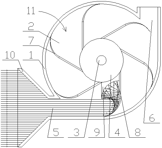
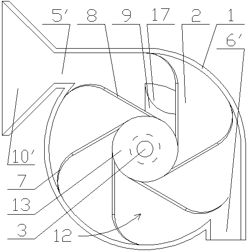
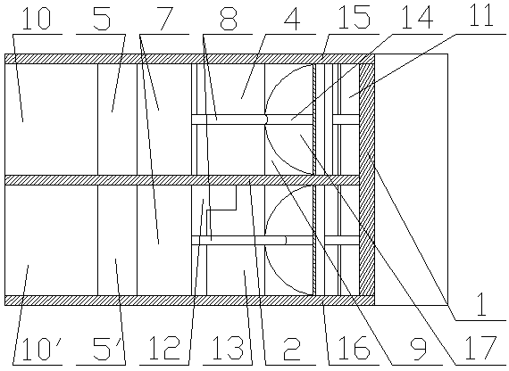
[0031] combine Figure 1~Figure 3It can be seen that the present invention includes a cylinder 1, the two ends of the cylinder 1 are respectively fixed with an end plate A15 and an end plate B16, and the middle part of the cylinder 1 is fixed with a partition 2, and the partition 2 divides the cylinder. 1 is divided into a booster cavity 11 and a generator cavity 12, the booster cavity 11 is provided with a booster 4, the generator cavity 12 is equipped with a generator 13, the booster 4 and the generator The outer rotor of the machine 13 is connected by transmission and rotates in the same direction around the generator stator shaft 3. The generator stator shaft 3 is fixed at the axis of the cylinder body 1. The circumferential surface of the speed increaser 4 and the generator 13 A plurality of blades 7 are evenly distributed on the outer rotor circumference of the cylinder body 1, and the side walls of the cylinder 1 are respectively provided with an air inlet and an air ou...


PUM


Abstract

The invention discloses a vehicle-mounted wind power generation energy complementation cruising device. A partition plate is fixed in the middle in a barrel and divides the interior of the barrel intoa speed increaser cavity and a generator cavity. A speed increaser is arranged in the speed increaser cavity, and the generator is arranged in the generator cavity. The speed increaser and an outer rotor of the generator are in transmission connection and both rotate around a generator stator shaft in the same direction. The generator stator shaft is fixed to the axis of the barrel. Multiple blades are evenly distributed on the circumferential face of the speed increase and the circumferential face of the outer rotor of the generator. An air inlet and an air outlet are arranged on the side wall of the barrel. In the direction of airflow in the barrel, the air outlet is located on the rear side of the air inlet, and the air inlet direction of the air inlet is the tangential direction of the position where the blades pass through the air inlet. From the above structure, by means of the vehicle-mounted wind power generation energy complementation cruising device, the barrel is divided bythe partition plates into the speed increaser cavity and the generator cavity, the power generation efficiency is improved, and the vehicle speed lower limit value needed for efficient power generation is reduced.

Description

technical field [0001] The invention relates to the technical field of vehicle-mounted wind power generation, in particular to a vehicle-mounted wind power generation device for supplementing energy and endurance. Background technique [0002] In response to the national new energy policy, energy saving and emission reduction, people need to develop sustainable new energy. In this way, solar energy, wind energy, geothermal energy, etc. , the faster the driving speed, the greater the coefficient of wind resistance and the greater the wind resistance. If the wind resistance is not utilized, it will be wasted. When the vehicle is running at high speed, the air will flow relatively to generate wind resistance. Using wind power to generate electricity, and then The electric energy is stored in the battery of the vehicle, so as to provide electric energy for the ignition system, lighting system, air conditioning system, etc. on the vehicle. [0003] The efficiency of the wind ene...

Claims


Application Information

Patent Timeline
IPC IPC(8): F03D9/25F03D9/32F03D3/04F03D3/06
CPCF03D3/0427F03D3/061F03D9/25F03D9/32Y02E10/728Y02E10/74
Inventor 张亚明张清皓
Owner 张亚明
Why Eureka
Try Eureka