Non-penetrating type hydraulic valve piston device
A non-penetrating, piston technology, applied in the direction of valve device, valve operation/release device, sliding valve, etc., can solve the problems of casualties, small valve stem diameter, seal leakage, etc., to achieve safe and reliable sealing performance and ensure system safety , the effect of easy installation
- Summary
- Abstract
- Description
- Claims
- Application Information
AI Technical Summary
Problems solved by technology
Method used
Image

Examples
Embodiment 1
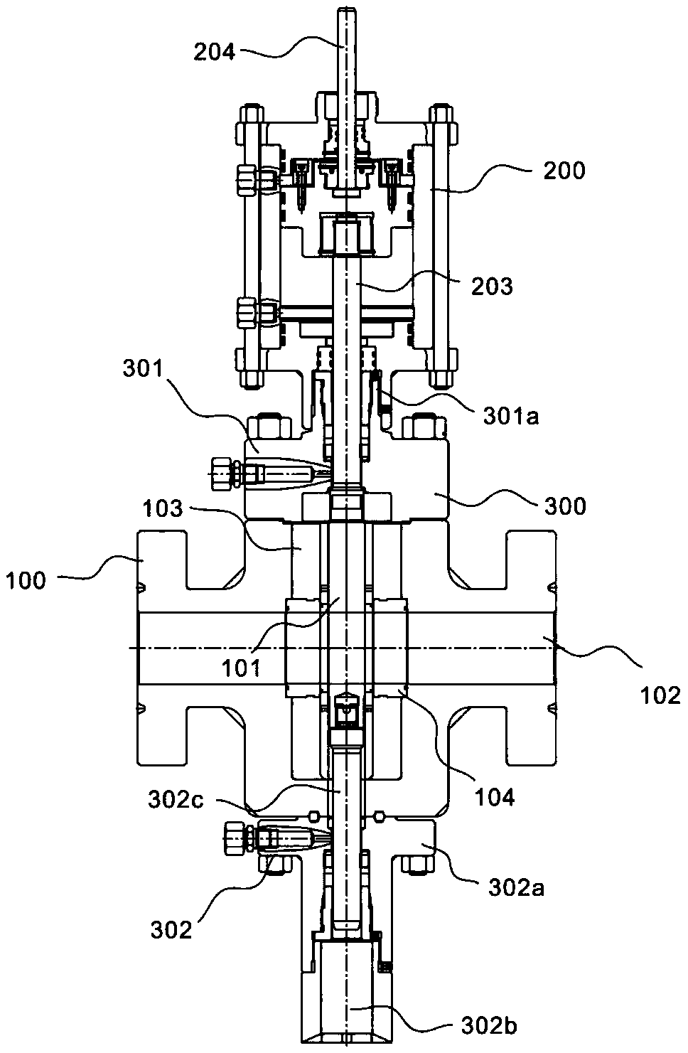
[0034] Such as figure 1 , which shows a schematic diagram of the overall structure of a flat valve system with a non-penetrating piston in this embodiment, including a flat valve 100 , a piston unit 200 and a valve cover unit 300 . Specifically, the system includes a flat valve 100 , a piston unit 200 arranged at the upper end thereof for driving the flat valve 100 to open or close, and a valve cover unit 300 used for capping the flat valve 100 and arranged at both ends thereof. Further, the flat valve 100 is a sliding valve whose closing part is a parallel gate, and its closing part can be a single gate or a double gate with a stretching mechanism in between, and the pressing force of the gate to the valve seat is It is controlled by the medium pressure acting on the floating gate or floating valve seat. If it is a double gate flat gate valve, the expansion mechanism between the two gates can supplement this pressing force, and the flat gate valve can be divided into two type...
Embodiment 2
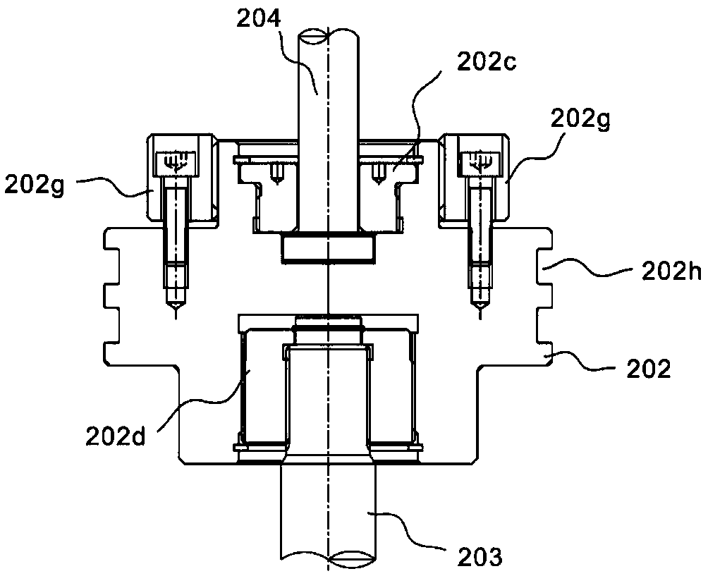
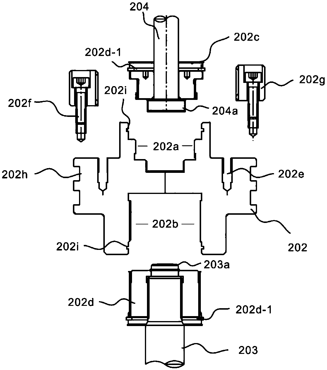
[0037] refer to Figure 2~4 In this embodiment, in order to achieve a more stable connection between the piston and the valve stem, so that it is not easy to loosen in the up and down direction, the difference from the first embodiment is that the piston body 202 also includes upper and lower ends. The upper installation cavity 202a and the lower installation cavity 202b are provided through, and the upper fixing part 202c and the lower fixing part 202d respectively match the contours of the two cavities. Specifically, the system includes a flat valve 100 , a piston unit 200 arranged at the upper end thereof for driving the flat valve 100 to open or close, and a valve cover unit 300 used for capping the flat valve 100 and arranged at both ends thereof. Furthermore, the plate valve 100 is a sliding valve whose closing part is a parallel gate, and its closing part can be a single gate or a double gate with a stretching mechanism in between, and the pressing force of the gate aga...
Embodiment 3
[0043] refer to Figure 5-6For illustration, this embodiment adopts a hydraulic drive method, so this embodiment is different from the above embodiments in that a pressure unit 400 connected to the piston is also provided. The pressure unit 400 connects with the upper inlet pressure port 205 through the oil circuit It is connected with the lower inlet pressure port 206 to push the piston body 202 to move up and down. The oil line route can be, for example, a pressure-resistant rubber hose line with a layer of steel wire sandwiched in the diameter, and the length can be selected by the user. Specifically, the system includes a flat valve 100 , a piston unit 200 arranged at the upper end thereof for driving the flat valve 100 to open or close, and a valve cover unit 300 used for capping the flat valve 100 and arranged at both ends thereof. Furthermore, the plate valve 100 is a sliding valve whose closing part is a parallel gate, and its closing part can be a single gate or a dou...
PUM
 Abstract
Description
Claims
Application Information
 - R&D
- Intellectual Property
- Life Sciences
- Materials
- Tech Scout
- Unparalleled Data Quality
- Higher Quality Content
- 60% Fewer Hallucinations
Browse by: Latest US Patents, China's latest patents, Technical Efficacy Thesaurus, Application Domain, Technology Topic, Popular Technical Reports.
© 2025 PatSnap. All rights reserved.Legal|Privacy policy|Modern Slavery Act Transparency Statement|Sitemap|About US| Contact US: help@patsnap.com