
Hydrogenation method and system suitable for filling pressure of 35 or 70 MPa

A hydrogenation system and pressure technology, which can be applied to the method of container discharge, equipment loaded into pressure container, equipment discharged from pressure container, etc., can solve the problem of high risk, low utilization rate of hydrogen compression equipment 3', high pressure There are many problems such as the number of hydrogen storage bottles, which can reduce the risk, reduce the number, and improve the reliability.

Active Publication Date: 2019-01-04
DONGFANG BOILER GROUP OF DONGFANG ELECTRIC CORP
View PDF10 Cites 17 Cited by
  • Summary
  • Abstract
  • Description
  • Claims
  • Application Information

AI Technical Summary

Problems solved by technology

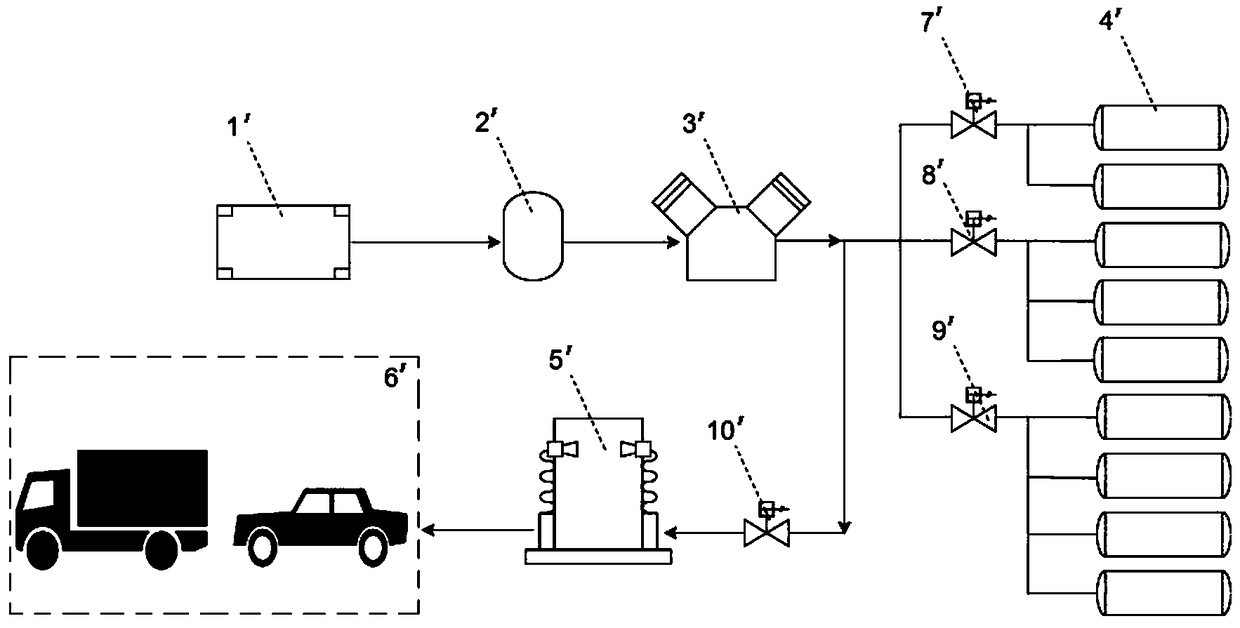
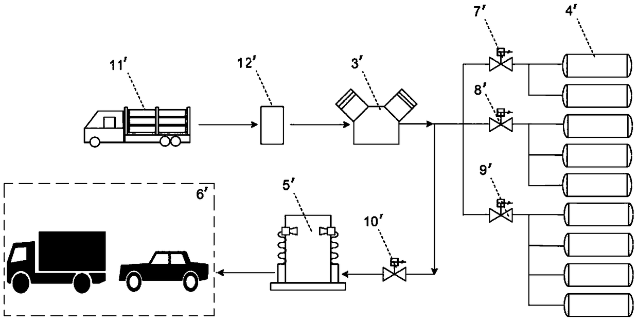
[0011] (1) Because the hydrogen filling port and the hydrogen output port of the hydrogen storage bottle group 4' are the same port, when the hydrogen storage bottle group 4' supplies gas to the hydrogenation machine 9', the hydrogen compression equipment 3' cannot work, and the hydrogen gas The utilization rate of compression equipment 3' is low
[0012] (2) Although it is artificially divided into three grades of high, medium and low pressure, the rated working pressure of each hydrogen storage bottle in the hydrogen storage bottle group 4' is the same as 45MPa or 87.5MPa. Big

Method used


Image

  • Hydrogenation method and system suitable for filling pressure of 35 or 70 MPa
  • Hydrogenation method and system suitable for filling pressure of 35 or 70 MPa
  • Hydrogenation method and system suitable for filling pressure of 35 or 70 MPa

Examples


Embodiment

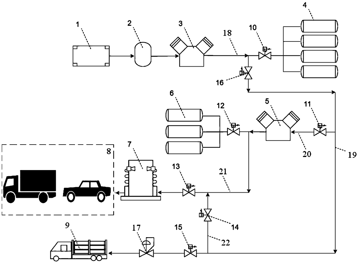
[0070] The specific structure of this embodiment is as image 3 As shown, in this embodiment, the injection pressure is 35MPa and the hydrogenation unit 7 is a low-pressure hydrogenation machine with an injection pressure of 35MPa as an example for illustration.

[0071] The 0.6-3MPa hydrogen produced by the hydrogen production unit 1 in the station is temporarily stored in the buffer tank 2, and after being pressurized to 15-20MPa by the low-pressure hydrogen compression equipment 3 (such as a compressor or pump), it is stored in the low-pressure hydrogen storage unit 4 Among them, the low-pressure hydrogen storage unit 4 is composed of several hydrogen storage bottles with a rated working pressure of 20MPa. The 15-20MPa hydrogen in the low-pressure hydrogen storage unit 4 is further pressurized to above 40MPa (such as 45MPa) by the high-pressure hydrogen compression unit 5, and then stored in the high-pressure hydrogen storage unit 6. The high-pressure hydrogen storage bottl...


PUM


Abstract

The invention discloses a hydrogenation method and system suitable for a filling pressure of 35 or 70 MPa. The hydrogenation system comprises an in-station hydrogen production unit, an external hydrogen supplying unit, a buffer tank, a low-pressure hydrogen compression unit, a low-pressure hydrogen storage unit, a high-pressure hydrogen compression unit, a high-pressure hydrogen storage unit and ahydrogenation unit; and the hydrogenation method fills hydrogen by using the hydrogenation system. Compared with the prior art, a hydrogen source of the invention comprises in-station hydrogen production and external hydrogen supply, which improves the reliability of a hydrogen filling station; when in-station hydrogen production equipment is out of service or the output does not satisfy hydrogenconsumption of the hydrogen filling station, a long tube trailer is used to supply hydrogen to the hydrogen filling station for replenishment; when in-station hydrogen production capacity exceeds thehydrogen consumption of the hydrogen filling station, the empty long tube trailer can be directly filled and sold with hydrogen; two kinds of compression equipment and hydrogen storage bottle groupswith different design pressure levels are provided to reduce the number of high-pressure hydrogen storage bottles and reduce the risk of hydrogen storage; moreover, various operations can be independent of each other and do not affect each other.

Description

technical field [0001] The invention relates to the technical field of hydrogen energy, and more specifically, relates to a hydrogenation method and system suitable for filling pressure of 35 or 70 MPa. Background technique [0002] As an efficient, clean and sustainable "carbon-free" energy, hydrogen energy has attracted widespread attention from all over the world. The transportation field dominated by hydrogen fuel cell vehicles is one of the important directions of hydrogen energy utilization. At this stage, the bottleneck restricting the development of hydrogen energy utilization in the transportation field is mainly the construction of hydrogen refueling stations, and the lack of hydrogen refueling infrastructure has become the biggest obstacle to the development of my country's hydrogen energy industry. [0003] The sources of hydrogen in hydrogen refueling stations are mainly divided into two types: external hydrogen supply and in-station hydrogen production. In-sta...

Claims


Application Information

Patent Timeline
Patent Type & Authority Applications(China)
IPC IPC(8): F17C5/06F17C7/00F17C13/00F17C13/04F17D1/02
CPCF17C5/06F17C7/00F17C13/00F17C13/04F17D1/02F17C2265/065F17C2265/063F17C2225/0123F17C2223/0123F17C2221/012Y02P90/45Y02E60/34Y02E60/32
Inventor 庄原发张定海杨锦郑国庆李重霖王晓亮
Owner DONGFANG BOILER GROUP OF DONGFANG ELECTRIC CORP
Learn More